TransportIn doesn't react to a product

Hi!
I am having a problem with transporting in a product from the component container to a process node
I have one process node Create the product, a manually programmed robot move the product to the Process node I am having trouble with.
Both of the process nodes are set to transport in and out to the component container.

Do you have any idea of what the problem can be?
My version is 4.5
Ackmontering.vcmx (1.8 MB)

The annoying thing is that the manual programing was my backup choice, i first tried to get all of the pieces to be automaticly transported to the second process node, but the robot would only move the first one.

Thanks for any help!

Your robot needs a transport controller if you want to use it with the automatic motions of process modeling. The processes are intended to be used with transport controllers handling the transportation from one process to the next.
This ‘traditional’ robot programming approach you are now using is not intended to be used with process modeling.

My advice is to focus on either robotics or process modeling. Mixing them like this is prone to errors.

If you really want to mix PM and robot programming, you could go to the robot signal action properties and set the ExcludeReleasingTo as follows:

This should prevent the robot from releasing the part on the fixture or on the table, and the part is placed in the process node instead.

Just note that when the Transport Out is triggered, the robot does not get any signal since it is not connected to a transport controller. You could add a new signal to the process node and use SendSignal statement instead to signal the robot that the task is done.

Thank you for your quick respons! Awesome feedback and info also.
Two questions:

Did the process node take in the product when you set up the exclude releasing option? I did as the picture but it did not work out for me…

Anyways, if i choose to just focus on the PM stuff, do you know how to get the robot to move all the pieces to the process node for assembly? do i need different flows for every single piece?

I did some changes if you want to take a look. Whatever i try i can’t get the assembly to work, i haven’t grasped everything that is needed for a successful assembly yet…

Ackmontering.vcmx (2.0 MB)

Thank you!

Hey Oskar,

There’s a couple of ways of doing assemblies so let’s check one of them. First you should begin by defining an assembly in your product editor tab in Process Modelling. This can be seen in figure 1.


Figure 1

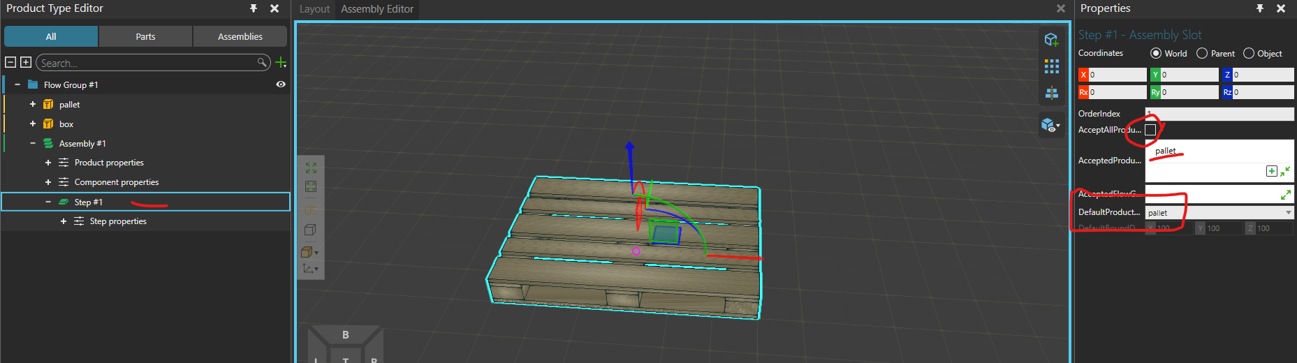
Click the pen next to “Assembly #1”. The pen appears when you hover your cursor on top of the assembly. This will open the assembly editor. The assembly editor, seen in figure 2 should then be configured with proper steps, products and visualization. Please note that visualizing the first step as a pallet does not guarantee that the first step in the assembly is actually a pallet unless you filter every other product and explicitly set that the first step is a pallet.


Figure 2, notice the Step #1, the unticked “AcceptAllProductTypes” and the “DefaultProductType” which is only for visualization

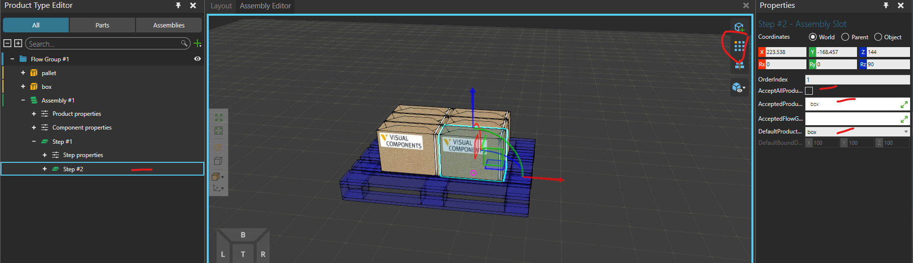
Next we need to add a new step, click mouse 2 (RMB) on top of the step #1 and add a step. You should then see the first or earlier steps in ethereal form, while having a yellow cube in the middle. This yellow cube is for visualization, so let’s first lift it on a proper spot (e.g. on top of the pallet) and then let’s configure the box by clicking on it. We can also select patterns. The configured setup is seen in figure 3.


Figure 3, remember to click the yellow box to select the actual product and not the step! You can set patterns on the top right of the assembly editor (circled in the figure)

We don’t really need to make any patterns but it does make the assembly a bit more logical. Regardless the assembly has now been properly defined and ready to be used. We can add more steps if needed.

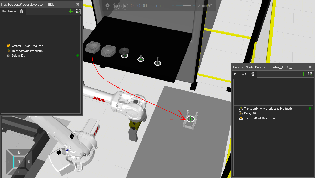
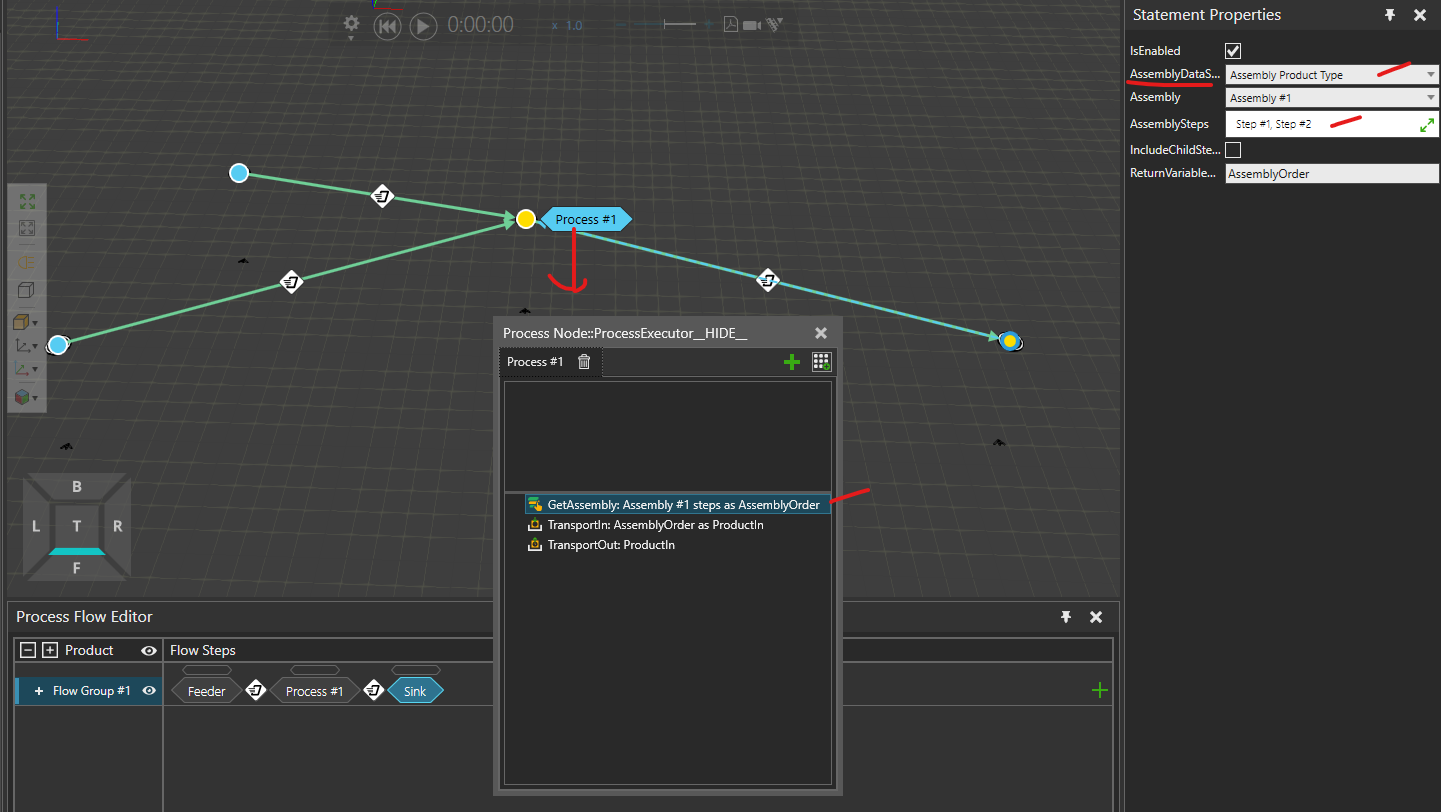
The next step is to actually build a layout that creates this assembly. Let’s do it with the simplest example, so no conveyors or robots, only two feeders into one process node into a sink. To start, bring two feeder processes and configure one of them to create pallets, while the other would create boxes. Next bring one process node and one sink process. The process node itself needs to be configured by adding one “get assembly statement” which basically gets the recipe for the assembly. Then we also need to reconfigure the “TransportIn statement” to transport in actual assemblies (in this case). This can be seen in figure 4.


Figure 4, the “get assembly statement” fetches us the recipe and in this case it is the recipe of Assembly #1, the value is then returned inside a variable named “AssemblyOrder” (or whatever the user wishes to rename it)

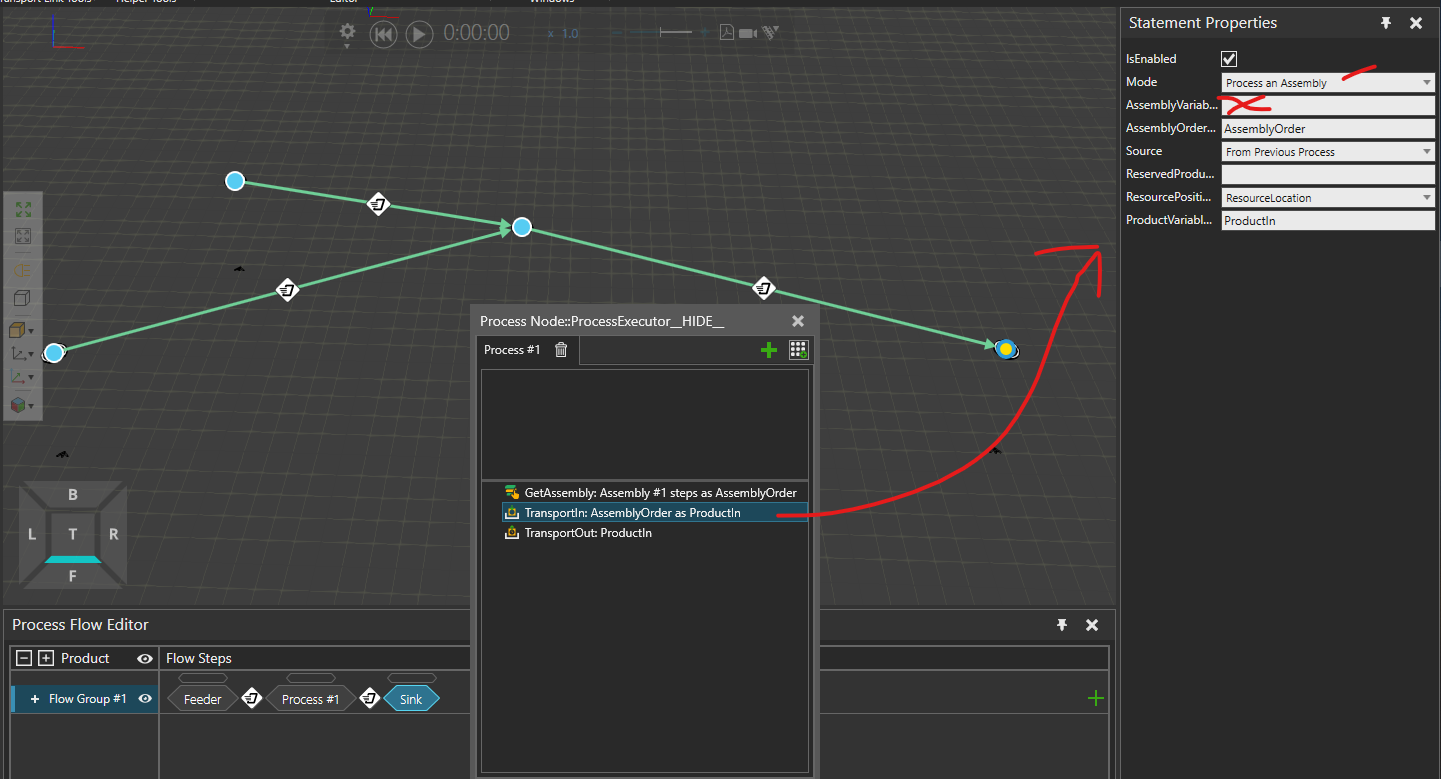
Next step is to reconfigure the “TransportIn statement”. Figure 5 shows the configuration.


Figure 5, we are creating a new assembly “on the spot” so “AssemblyVariableName” is left empty

Although all of these fly through the air, we can always use a robot to do this as well. Just add a transport controller and robot and make sure everything is close enough for the robot. Then change the transport link from interpolating transport to robot transport. As for the flow group itself, if your product doesn’t go through “different route” you can keep everything in one flow group.

Now we should be able to build assemblies. There are more examples within the template layouts of the software as well as in the academy itself.
https://academy.visualcomponents.com/?s=assembly

I have attached the simple assembly example here. I hope this helps!
assembly_simple.vcmx (1.3 MB)

Best regards,
Lefa

2 Likes

Hello,
I have another problem with transport my product. My robot can’t put part to assembly board. I think is problem with flow and process statements know where directly it is. Do you have any idea where and how resole this problem?


FRC Large Template 1 EX3.vcmx (54.0 MB)
Uploading: FRC_Large_Template_1_EX3.avi…

Best regards
Chris

Hi,

This layout has some… workflow issues and it is somewhat hard to debug. What I would recommend here is that you change everything to interpolating transport first and then figure out what is going on, also remove the redundant geometries (for debugging purposes you don’t really need these conveyors etc.).

One of the larger issues is seemingly the zero point(origin) of your circuit board. you can see that the board gets constructed “rather far” from the chassis feeder.

image

But maybe this is intended? While I appreciate that you have definitely tried on your own, reading this can be somewhat hard :slight_smile:

I have uploaded the layout back where I cleaned up some of the geos and the output doesn’t give out errors anymore, no clue how this is “supposed” to work though.

FRC Large Template 1 EX3.vcmx (48.7 MB)

br,
Lefa