I would like to make a component create generate couple of blocks but the problem is that when I browse the file with the blocks, the program says it is not a component but a layout.
Could you give me a hint how to model the blocks as a component so that a component creator could generate these blocks?
I will explain in more details what is my goal.
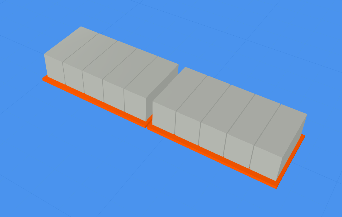
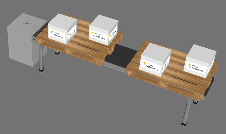
What I want is the blocks in grey are supposed to be taken by the robot, while the two plates in orange, that are under the blocks, are supposed to probably let’s say disappear when the blocks are taken from them.
The component creator is supposed to generate the two orange plates along with the grey blocks on top of them. The blocks and the plates will run on a conveyor after they are generated.
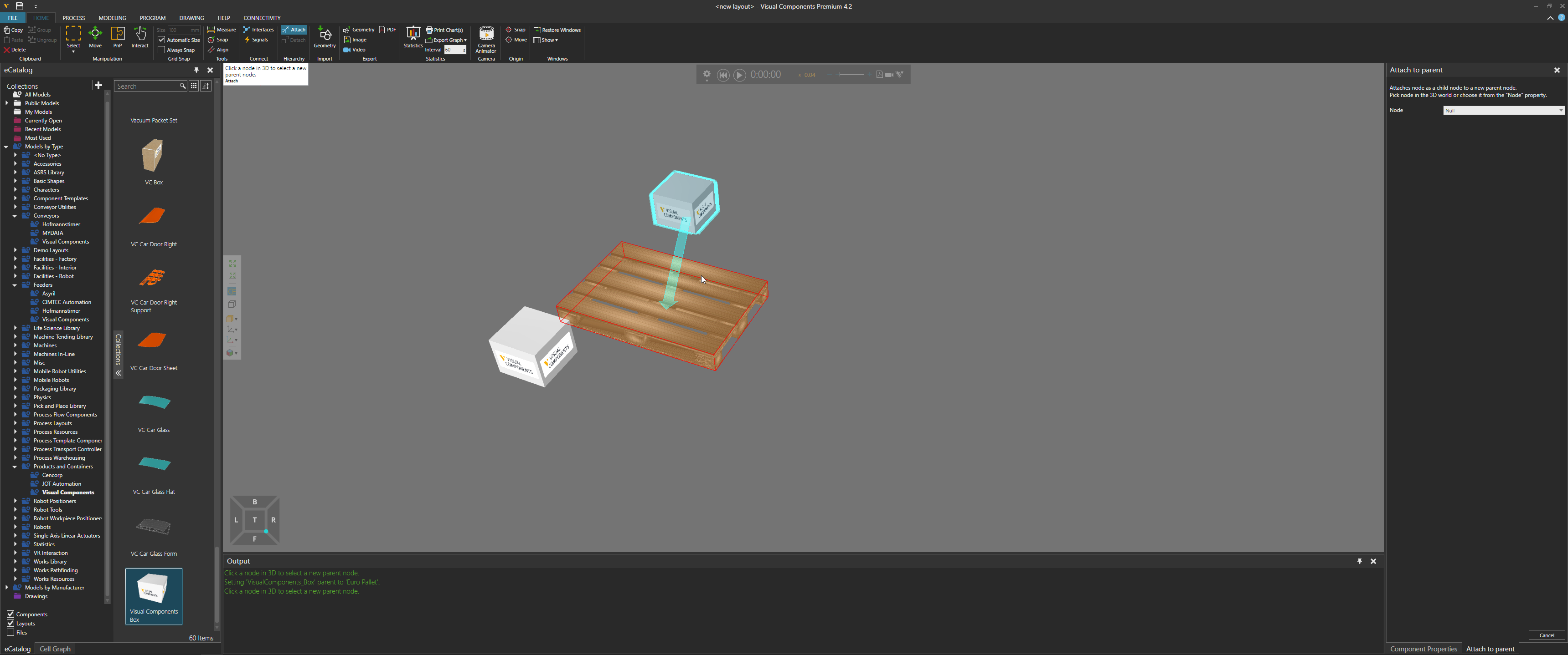
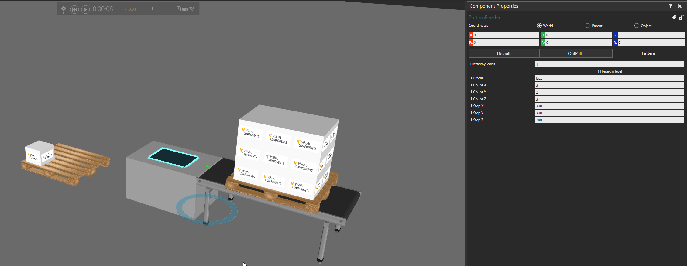
If I remember, you are rocking the KUKA.Sim… there are some components like pattern feeder in their eCat that can help you if you don’t want to model your own. One tip about the Component Creator is that it creates a component and ALL of its child components, i.e. the components you attach to the nodes of the component being created – see attached layout (creator makes the orange sled and boxes are attached to it.
If you are using VC product then there are lot of components in eCat that can do this for you. If you want to use scripting, you can use component container and creator to first make the orange bottom, and then create each box and attach it and transform it where you needed it. But there are components and other ways to do this without writing code.
I managed to create the component with the Compnent Creator and also attached a conveyor to it. The difficulty was to adjust the coordinate systems(frames) so that the component is generated in the right direction. The frames of the conveyor were a bit messy as well, I just rotated and moved them according to my needs in the Modelling Tab and I hope this will not change them in the conveyor file, it should only apply changes to the file I am currently working in, I guess.
The only problem is that when the robot grabs the blocks, it will also grab the bottom plate.
Could you give me some more hints about how to eventually make the robot take only the blocks but not the bottom plate?
You say that I should create the bottom plate first and then create each block. I think I should avoid writing code for now since I am not completely confident with the program yet. A hint how to approach the problem without writing code will be appreciated.
If the robot is grasping the bottom plate that means the detection volume size is too big for the signal action or the plate is attached to one of the blocks.
Select the robot, and then in Component Properties panel, near the bottom find a section “Actions Configuration” and the go to the output signal you are using to trigger grasp. Modify the detection volume size in Z-axis to maybe be 5mm and see if the plate is still picked up by robot after you run simulation.
Without writing code… there are many different ways. simplest is just added all the components to 3D world, attach them to bottom plate, save the plate as new component, and then create that new component. there are deprecated behaviors like pattern behavior, etc. but i do not recommend using them.
Works Process is referring to Works library of components that are only available in Visual Components eCatalog not in KUKA.Sim.
I guess my mistake is that, when I made the component first I created the bottom plate and then all the blocks attached to the bottom plate and then moved across the bottom plate according to my needs.
In other words all the blocks are referenced to the coordinate system of the bottom plate which makes them one component.
Basically the bottom plate and the blocks are one component and perhaps this is what makes the robot grasp everything. By the way my detection volume is 50 mm while the height of the block is 200 mm, therefore the robot should not detect the plate, but since the blocks and the bottom plate are one components, the robot does grasp them together.
What you suggest is to create the bottom plate in the 3D world and then what do you mean by “attach them(the components I guess) to the bottom plate”?
Do you mean attach the blocks utilizing links or something else?
I found out that Works Process is only available in Visual Components, I watched a tutorial and checked that there is no Works Process in KUKA Sim Pro.
In the layout I attached in earlier reply, the sled and boxes are different components, and I am only creating the sled. The boxes are created with the sled because they were attached as child components, and then saved with the sled.
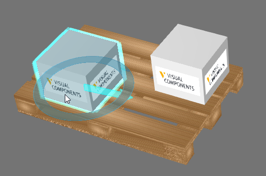
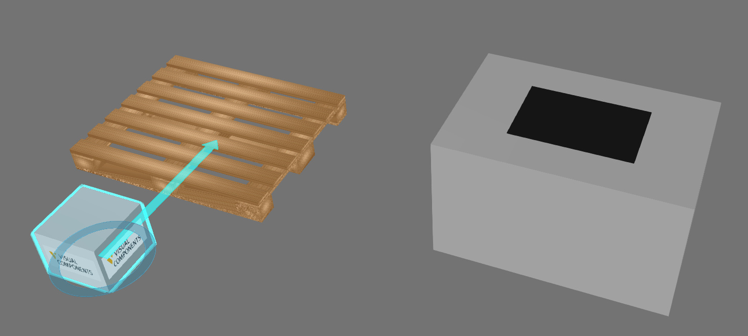
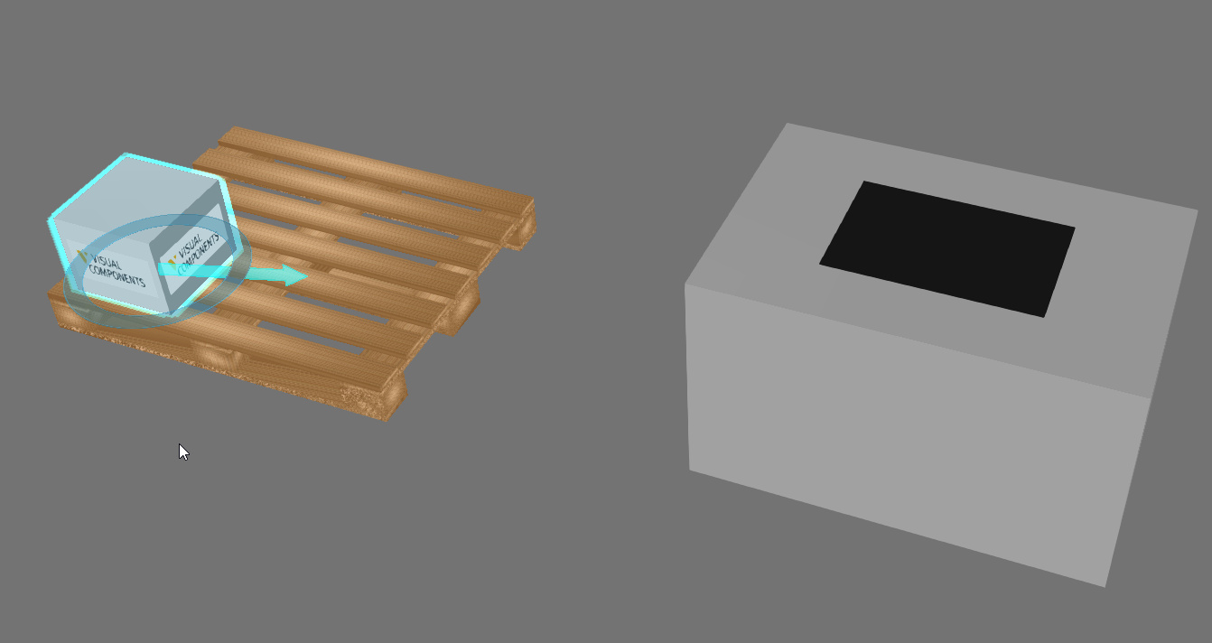
Let’s take a box and pallet from eCat.
Select the box.
On the Home tab, in the Hierarchy group, click Attach, and then attach the block to the pallet. The pallet only has one node, its root.
Now select the pallet and save it as new component… assuming you are using SimPro not SimLayout and have access to the Modeling tab. Remember, save it as new component.
Now use a feeder and conveyor, and make the feeder create your pallet/new component made in step
Good luck, friend. This is where I get off the bus, unfortunately, on this thread.
With hierarchy, it is like tree structures. And this topic has many roads to travel on. Basics are that component is created with its entire node structure, so if other components are attached to nodes in the component then those other components are also created. If you do not want that to happen, one solution is to detach the other components. And one thing to stress in component modeling is that geometry which should be considered its own product should be a separate component. As you mentioned, picking the geometry of component means the entire component is picked by the robot. If they are separate components, you can avoid that.
I managed to make it work before reading your post, I will try what you have suggested above, of course.
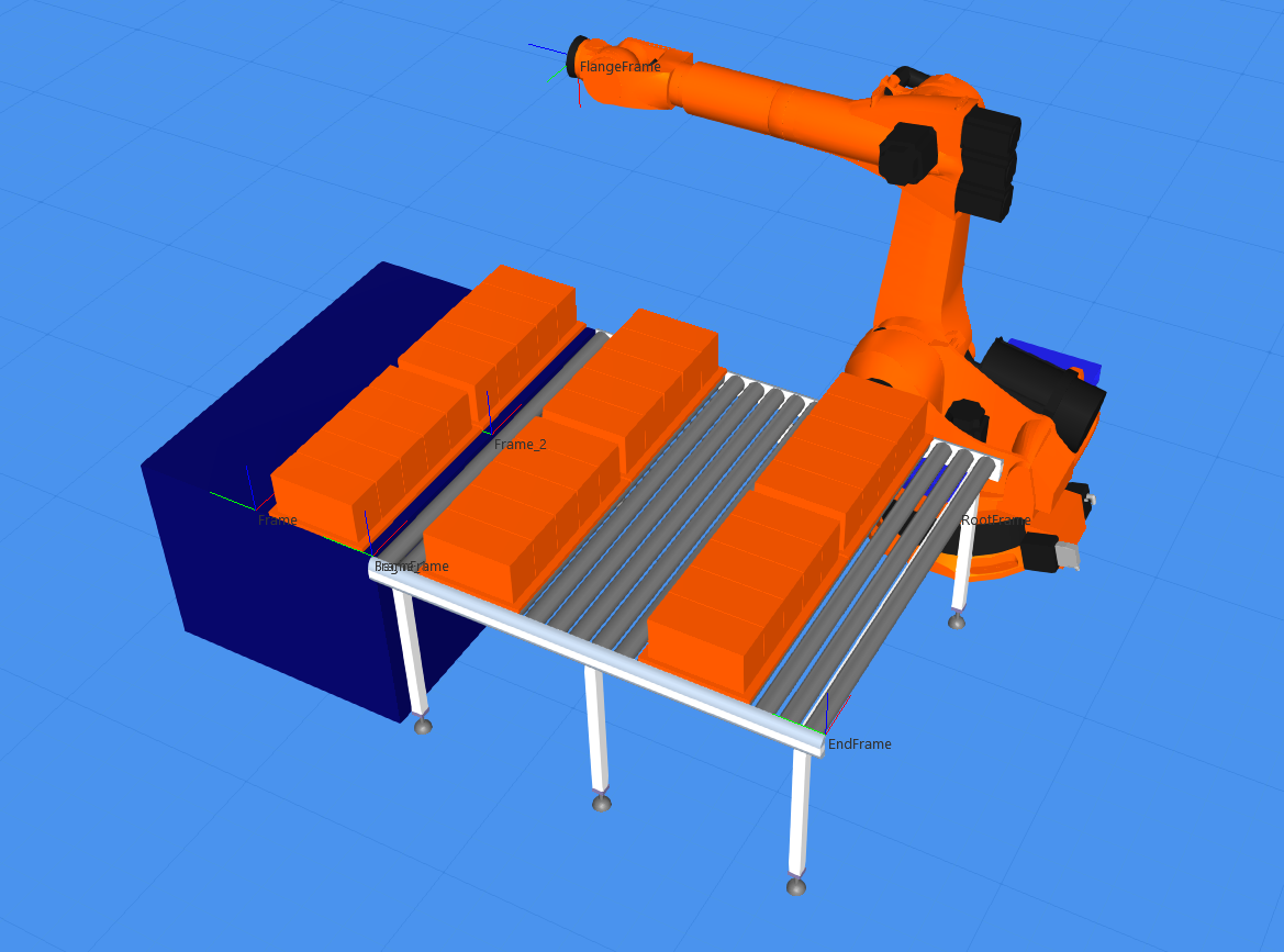
But something very weird is happening to the conveyor. You can see it in the picture.
I wired a signal from the robot output to the conveyor belt motor, so that when the robot puts two plates with blocks on the conveyor, the conveyor is supposed to start. But look how the two plate get unaligned to each other. The offset is just as much as the width of one plate.
Do you have an idea what could cause the plates to get unaligned?
Your suggestion kind of worked, the blocks are transported together throughout the conveyor, but I am still struggling with making the blocks not overlap each other in the end of the conveyor.
Basically I have a sensor in the end of the conveyor line which is supposed to stop the part(the blocks). The sensor works properly, it stops the blocks but the next blocks just overlap the first ones, I mean they do not stop behind the first blocks, they just overlap each other.
I turned off the Space Utilization and have Accumulation and Retain Offset turned on, as it is by default.
I tried to figure out, how to fix this myself, but I am still struggling.
I am sorry for bothering you so much with my struggles with KUKA Sim Pro, but if you can suggest any kind of manual or any other documentation about KUKA SIM Pro where I read about all these commands and features, it will be helpful for me.
Look at the attached video to visualize better what the problem is.
No worries. The Help file, specifically the Behaviors reference can help.
What you described should happen because the parts are not respecting the space of their bound boxes.
You could undo everything you did to the path, and modify the robot’s signal actions. Check for a subtab in the robot’s component properties, i.e. select the robot as component, and then go to Component Properties panel. In the subtab, there should be a property to release parts as bundle, e.g. the two blocks are released and attached to one another, so they would move together. That is assuming the are both picked at same time. In VC eCat there are helper components like bundler and debundler for what you described.
To save time, I would recommend you contact support.
Unfortunately still no success, I cannot see anything like “bundle” in the Signal Actions subtab.
I tried to assign Length, Width and Height in the Property section, since I was thinking that the blocks actually does not have its dimensions assigned somehow as a feature or property but still the blocks overlap.
I also tried to use a component from the library and see if the overlapping happens again but even components from the library overlap each other in the end of the conveyor.
I checked the Help File, it has nice description of all the behaviours.
I guess I will have to contact the support for more detail help.
I am still struggling with KUKA SIM Pro, but, of course, I will never give up.
These days I was at the site, mounting and initiating some KUKA Robots and did not have enough time to look at KUKA SIM Pro, I will get back to it tomorrow.
I was thinking about your suggestion about the Bundle Release Components, I actually do not pick the two plates with blocks at the same time. I pick the plates, along with the belonging blocks, one by one(one(1) orange plate with five(5) grey blocks on it) and then place them on the conveyor. Therefore your suggestion about turning the Bundle Release Components on probably will not work either.
What I could say now is that if I use only one conveyor the plates with the blocks stop exactly one after the other. I was also thinking if the problem could be in the conveyor settings namely the detection volume feature similar to the the gripper settings. Somehow the conveyor does not detect the object size when there are two or, perhaps, more components placed along the wide side of the conveyor.
I am still discussing the problem here since, probably, someone else will have the same obstacle in the future and hopefully they can learn how to fix it from here.
Are you trying to do this? Without doing any scripting and using components from KS eCat, I program robot to place crates side-by-side, turn on conveyor, and then sensor attached to conveyor stops things. Layout - Pick and Place Crates.vcmx (1.6 MB)
Yeah, I am trying to do something like this. I just want to keep creating crates until I reach a predefined amount which I count in the while loop. The crates are supposed to stop one after the other on the conveyor. Basically, when the first two crates are stopped by the sensor, the next two crates should stop just behind the first two crates and so on until the predefined number of crates is reached.
Perhaps it is a stupid question but why cannot I attach a sensor to a regular conveyor, it allows me to attach the sensor to the batch conveyor only? I do not see any difference between these two types of conveyors. In your layout you attached the sensor to a regular conveyor that is weird for me.
By the way the video is not active.
EDIT:
I figured out why I could not attach a sensor to a regular, straight conveyor. The reason was that the conveyor itself does not have the sensor interface in the behaviour section. I added Component Path Sensor behaviour, a Boolean Signal and a One To One Interface and now it works.
The way the conveyor is modeled in KUKA eCat is to not have One-to-Many interface for sensor connections, which is why I modified the conveyors in my layout. The video isn’t active because of some issue with Chrome and MP4 files on this forum. If you switch to edge you see it, but it is just a recording of the simulation of the attached layout.
You can observe now the crates 1 and 2 move on the conveyor with Space Utilization turned OFF and they move as they are supposed to - next to each other. Then I turned the Space Utilization ON and crate 3 stopped just behind crate 1 but look where crate 4 is. It is at one crate space behind crate 2, it should be just behind crate 2, next to crate 3.
If I keep going with Space Utilization turned OFF, the crates 1 and 2 stop at the sensor but the next crates just overlap with crates 1 and 2.
I hope you get a better visualization of what I am trying to achieve.
Yes, one suggestion is to use physics path in the out conveyor. The SignalActions property of the robot component allow you to release components to physics. Otherwise, you might need to do some scripting. Support or maybe others here can provide quick solution. If you share your layout with support, they can probably write a quick script for you, e.g. when signal from robot received, attach the components on path together.