Hello, I have a question.I created a robot and made the coordinate system, but the coordinate system did not match the center of the robot flange.What is the problem and what Settings do I need to change?robot.vcmx (33.0 MB)
Hi,
The kinematics properties do not match the offsets and joints in the node tree. I would suggest to look at this Academy tutorial and using some existing robot as template for modeling a new one:
https://academy.visualcomponents.com/lessons/model-an-articulated-robot/
-k
-
- TCP location is wrong, don’t know how to fix it,Can you help me fix the mistakeUntitled.vcmx (8.4 MB)
You put elbow-to-wrist offsets to L45X/Z when proper way to do it is to put it on L34X/Z. Like in this attached model:
AIR165-A.vcmx (8.5 MB)
-k
thank you very much!
I still don’t understand the kinematic properties with respect to the offsets and joints of the node tree, and this data has to do with the arm length of the robot, right?
When I used MechanismWizard_2020_09_08 to build the , the modeling prompted an error. I haven’t found the error yet! balance cylinder.vcmx (10.2 MB)
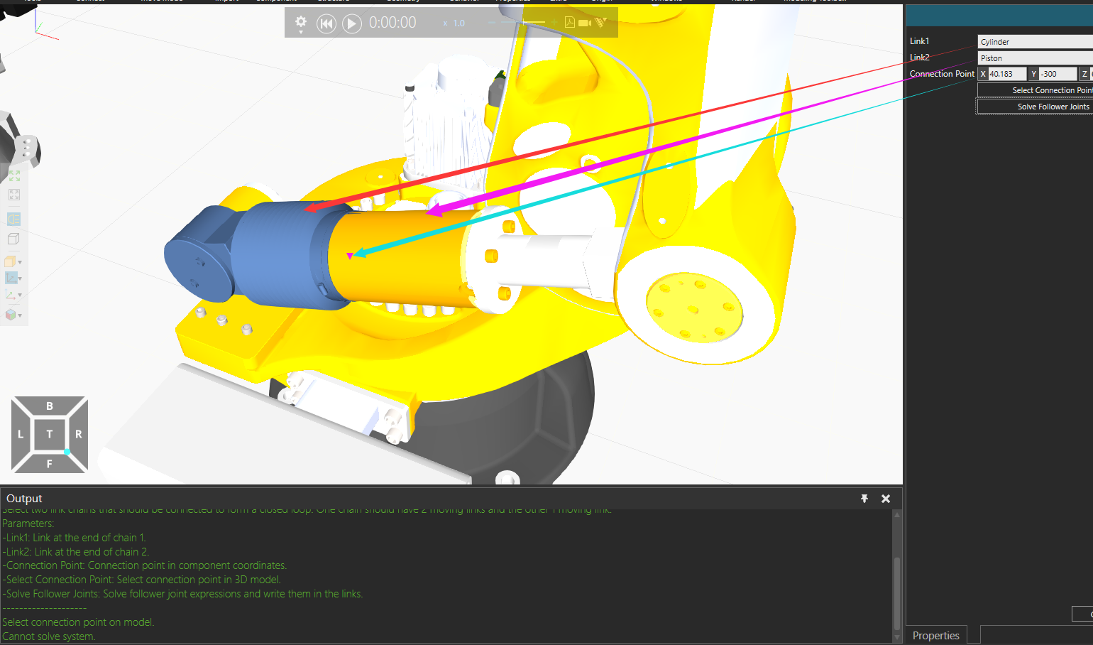
Mech Wizard doesn’t work because your robot joints are modeled as “Custom” joints and Mech Wizard doesn’t support those. You need to use rotational joint type for Axis2 and then the mechanism wizard works. Example of that is in the MW package example models (IRB6700). Custom joint types are the old way all robot joints were modeled going all the way back to before 4.X products were launched. Nowadays we prefer Rotational/Translational types for robots.
-k
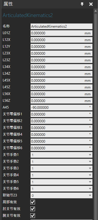
Check out this attached robot. It has all Kinematics properties coupled to the node tree. So for example in link “Axis 3” you see how the link offsets are directly the L23X/Z from kinematics. JointZeroOffset3 and JointSign3 affect the joint zero position and sign. Finally Coupling23 and Joint 2 properties affect how J2 is coupled to the joint value of axis 3.
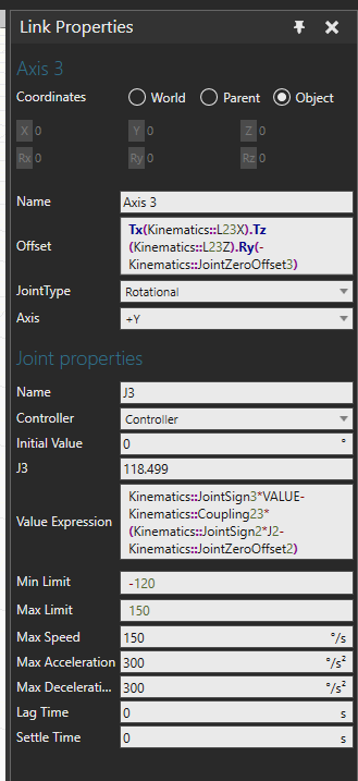
As you can see including every property in the link nodes results in very long offset and joint expressions. So generally you may not see full coupling in ecat robots. For example Coupling23 and Coupling456 usually is not used in link expressions and neither is JointSign which we set on the “Axis” property of the joint directly (e.g. +Y or -Y). So ecat robot links are a bit simpler than on this example model.
Note that in the example robot link structure is fully coupled to kinematics but geometry is not parametric. So changing Kinematics properties keeps the node structure in sync with kinematics and flange node moves correctly with the TCP but geometries in links become disjointed.
A2_Robot.vcmx (417.7 KB)
-k