I also was wondering has anyone been able to extract any data in relation to this connection? For example, extracting the XYZ coordinates from the robot in Visual Components when it is being driven by a server connection? I think maybe python might be needed for this, but I am unsure!
If I recall, at least with URSim there is little or no difference between target_q and actual_q values.
Maybe easiest way to extract joint values is through the statistics dashboard functionality and specifically the robot joint values template. For TCP location you would probably need some scripting to either copy those values to properties that can be recorded using the statistics dashboard, or collect and export them directly.
About actual_q vs target_q, I think it is mentioned in the Help file > Tasks > Connectivity > RTDE. Also, consider taking a look at how the UR robot components in the eCatalog are modeled. About extraction, both the UR RTDE and Stäubli connections can be used for trace analysis. I have seen it done with Stäubli connection using SRS and other apps. I am very rusty with PolyScope and UR scripting, and I have never tried to do remote call, for example, to track data. On VC side, you can add a script to robot to record motions and tcp position at a given rate, for example using vcHelpers.Robot2 module (simple but costly way is to monitor joint value changes).
I did try to test safety IOs with the connection back in spring, but couldn’t get it to work and I just assumed it was configuration issue on my part plus hack in UR program to trigger wait for input in middle of blended motion. For example, I was testing to see if safety IO from simulation could trigger stop in controller.
Thanks for the reply. I have not found any more information that states the difference between target and actual, so I will go with that for now. I actually was unfamiliar with the statistic dashboard until now, and in a way it was exactly what I was looking for! There appears to be an extensive list of properties to plot, but as you stated it looks for the TCP will need scripting, as this is not a property option (unless I am missing it, I also selected the tool itself and it wasn’t an option). I am quite unfamiliar with python & python scripting in VC, so I will try and look in to this. Thanks!
Thanks for this information! I had a look in to the help file, and it does mention target_q, but not with any context around what I was looking. I also am unsure on the connected variables, as from what I can read, you can connect other variables, but I am not sure why or what you would get from this? Additionally I read that ‘255 input recipes can be defined per client’, but I also am unsure what this means, if you have any insight?
Python & python api in VC is not something I have much experience in so I will have to look in to this and see if I I can extract information such as the TCP, as it is not offered in the statistics plots from what I can see (just recently came across these too). Just to get me started, is there much of a difference between vcHelpers.Robot and vc.Helpers.Robot2, I had a scroll through and couldn’t spot anything immediately different?
It is a bit of maze. vcHelpers.Robot is deprecated, so don’t use it. use vcHelpers.Robot2, and VC support probably has a script they can share on how to track the TCP.
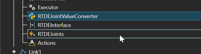
with the actual vs target, my understanding of the documentation is that it relates to read/write access to controller that is supported in Visual Components, and the values of certain variables don’t have matching types, which is why UR robots use a script that converts and updates joint values of simulated robot immediately on change notification.
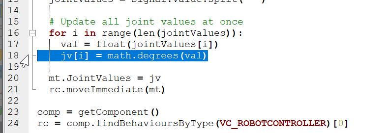
Here joint value received from controller is converted to degrees
About the recipe, client in this case refers to server connection to controller/polyscope. my understanding is you can have multiple connections, and each connection on VC side can have max of 255 mapped variables that are “server to simulation”, for example input from controller. outputs from simulation to server for all connections combined are capped at 255, so 300 inputs from sensor signals in simulation cannot be mapped to controller.
and i agree it would be good to have chart in dashboard that report tcp data.
No, the input recipe limit actually just means that if you are connected to UR and add / remove variable pairs in the simulation → server direction, each change (or activation of the variable group) creates a new input recipe and you will eventually run into the 255 limit. After this limit is reached the communication won’t work as expected and you just need to disconnect from UR and reconnect to have the “counter” reset to 0.
Would you be able to give me a brief description of what a recipe is and an example of 1 of the 255 mapped input variables? I am quite new to this, so what I understand from the documents and videos, the RTDEJoints in the modeled robot is paired to the target_q of the non visual components simulation robot. And this is the only pair that can be made? I might be thinking about this completely wrong, so any help is appreciated!
The Connectivity feature in VC implements version 1 of the RTDE protocol, which allows reading a wide variety of information from the UR robot controller, and also writing back a more limited set of variables. Which subset of the available information you want to use and for what is up to your use case and simulation setup.
The usual case is reading the current joint values and also binary output values so you can create and test a UR robot program in the context of the 3D simulation environment that VC can provide. This is in contrast to either programming the robot using real hardware, or having to program the robot “blindly” and then probably still need lots of time testing with real hardware.
The Connectivity feature allows free pairing of “server” variables to VC simulation signals, properties, signal maps, and joints. Your simulation logic can then be built to react to changes in any of those, or you could e.g. just collect the values and process them in some way using Python scripts.
Maybe you wanted to e.g. check that TCP speed of the UR robot doesn’t go over some unsafe threshold in your collaborative robot setup?
The vector-form TCP velocity is available from the RTDE interface directly, so you could connect that to e.g. some VC properties and then use a script to calculate the speed and alert you when it goes over your safe limit. This particular thing could probably be implemented on the UR controller side as well, but more complex use cases will benefit more from the VC simulation environment.