Hello everyone,
I am a student currently working on my Bachelor’s Thesis project (POLYTEHNIC UNIVERSITY OF BUCHAREST, FACULTY OF INDUSTRIAL ENGINEERING AND ROBOTICS). My goal is to recreate a complex BIW (Body in White) Welding Cell simulation based on a real-world reference.
Context: I am rebuilding this cell based on this video: https://www.youtube.com/watch?v=48m_RvzMCcM
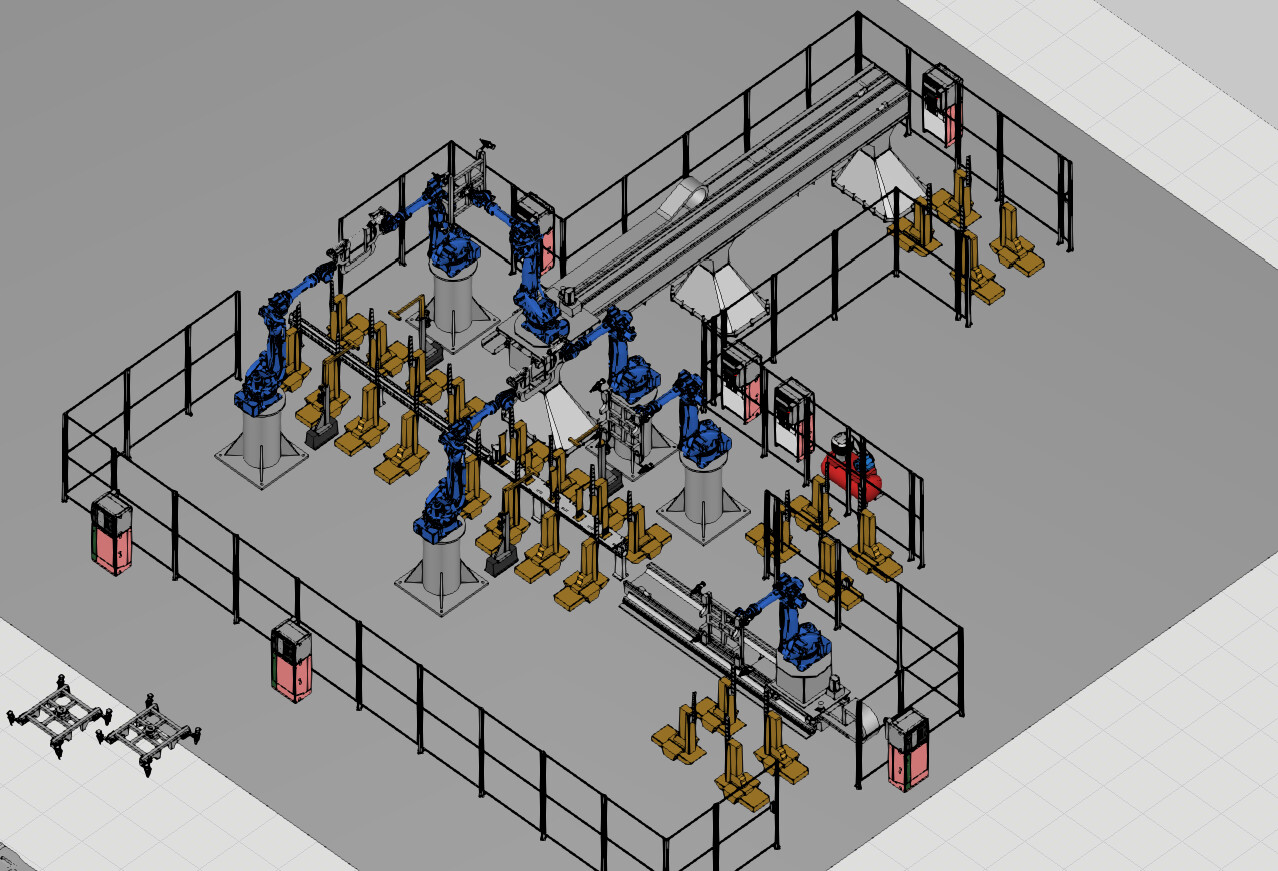
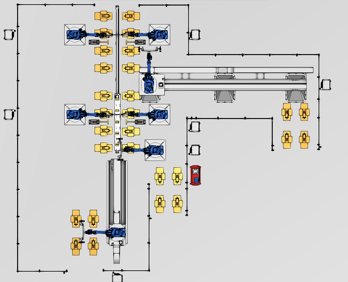
The Challenge: I have successfully imported and configured my own CAD geometry (Robot 7th Axis, Custom Linear Rail, Custom Lifters/Positioners). However, I am completely stuck on the Process Modeling phase. I do not understand how to make my custom imported geometry work with the Process Flow. I don’t want to replace my models with standard eCatalog components (like generic conveyors or feeders) because I need the specific components of my design.
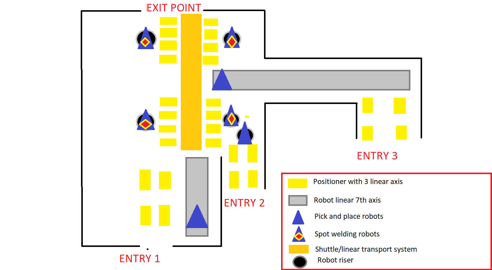
My Layout & Workflow (See attached screenshots):
-
Inputs/Outputs: 3 separate entry points for BiW parts, 1 exit point.
-
Handling: 3 Handling Robots pick parts from 4 linear positioners and place them onto the central line.
-
Process Station 1 (Lift & Weld):
-
A set of 4 synchronized linear positioners (custom modeled) must receive the parts.
-
Logic: They LIFT the assembly → Spot Welding Robots weld it → They LOWER the assembly onto a central shuttle.
-
-
Transport: Custom Linear Rail (Shuttle) transports the assembly to the next zone.
-
Process Station 2:
- Another set of 4 Positioners LIFTS the part from the shuttle → More welding → LOWERS it back.
-
Exit: Shuttle moves to exit.
My Questions:
-
Custom Geometry as Process Node: Since I am not using eCatalog parts, what Behaviors (Transport Node, Process Executor, etc.) do I absolutely need to add to my custom CAD to make it recognized by the Process Flow?
-
The “4-Legged” Station: How do I treat the 4 separate positioners as a single logical station for the simulation? I need the part to sit on all 4 of them, but logically be processed as one unit.
-
Complex Sequence: How do I program the Transfer → Lift → Weld → Lower → Transfer sequence in Process Modeling?
I have attached screenshots of my current layout below.
Any guidance, tutorials, or examples of setting up Process Flow on purely custom geometry
would be incredibly helpful for my graduation project.
Thank you in advance!
CELULA MANIPULARE SUDARE BiW GP225.vcmx (11.0 MB)