Hi,
I would like to first give you an overview of my project before asking the question. The task of the project is, The station picks workpieces from a conveyor belt (connecting belt) onto pallets. Empty pallets are placed on the intermediate storage locations via the input chute. The robot picks the pallets according to the customer’s requirements. Finished pallets are placed on the output chute for further processing. The complete handling of the workpieces and the pallets is carried out by a robot.
my question is, I have so far no idea how to control the Robot Mitsubishi (RV-2F) through a PLC? I have already connect the inputs and outputs with Tia-Portal using the connectivity option, but how can I exactly control the movements of Robot?
So is the PLC controlling the robot? On the simulation side, each axis of robot should have a VALUE property. You can use the VALUE property to get/set the axis/joint value. On the PLC side, I am not familiar with the Mitsubishi motion blocks, etc., so to move the robot is the connected PLC providing the current position of robot or axis values, albeit individually or as array?
Hi,
how can I use the Value property, I have not found it?
I have not yet programmed the robot in the PLC, until now I am trying to understand how to set the current position and axis values of the robot.
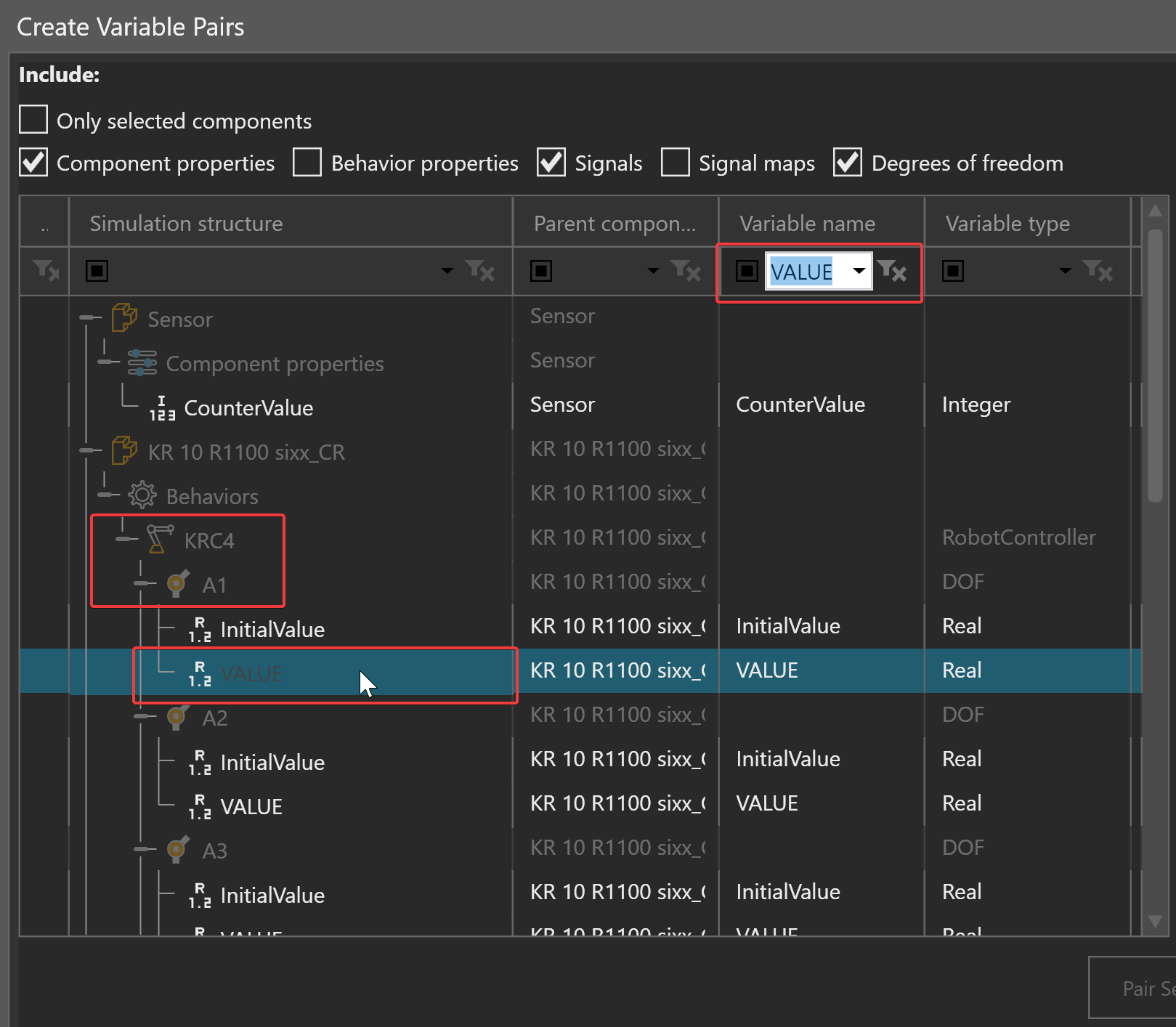
VALUE is the current joint value of a link/node that has a defined joint. In Visual Components, a node or link in your robot has a degree of freedom object, and it is that object that defines the joint properties of the node.
Here you can see the joints associated with the robot controller are listed and the Dof property of VALUE can be paired to a variable in the connected server/PLC.
Hi,
all right, that means each joint is controlled individually by PLC. one more question please, do you know exactly how this value is represented in the PLC? whether it is a Normal Real Value, or I get a value with (X;Y;Z) values?