All the necessary files for this test is attached here as well (download from attachment). You should go to the following link to see the total setup instruction video.
Nice tutorial!
Have you tried measuring what kind of end-to-end latency (response time) you can get with this communication setup?
VC <-> KepServer should be pretty fast, but how fast is the communication through NetToPLCSim and response time of PLCSim itself.
@TSy, no i didn’t test communication speed in between NetToPLCSim and PLCSim, with my first 2 tests it seems pretty fast (only 5-10 variables). I don’t know the situation when there might be 300-400 variables communicating with KepServer. It would be interesting to see the latency in between .
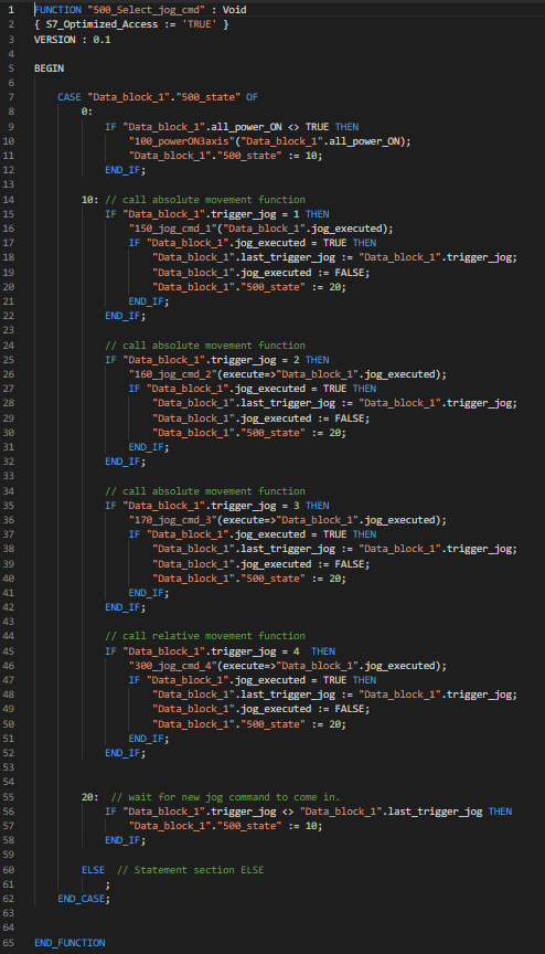
Here is Part-2 of the communication test. This 2nd example will also give the user idea of using Technology Object > Motion Control library of Siemens TIA Portal V15. SCL code for Motion Control attached in ZIP folder.
This is how the main function of this program looks like.
Here is part-5 (part-3 & part-4 will come within a week) of the series. It’s a rich example of how to prepare simulation components behavior with python script & then structured text PLC code example. You will find all related component *Layout *Description *PLC code from following link:
Here is part-3 of the series. It’s a rich example of how to prepare simulation components behavior with python script & then structured text PLC code example. You will find all related component *Layout *Description *PLC code from following link:
Here is part-4 of the series. It’s a rich example of how to prepare simulation components behavior with python script & PLC code example with Structured Text(ST). You will find all related component *Layout *Description *PLC code from following link:
Are you using Siemens PLC for your use case? If Yes then do you have Siemens PLC Sim? with newest Visual Components version you don’t need to use Kepware as middleware anymore, you can directly connect to Siemens PLC Sim.
Do you have lots of python While loops running inside the components in Simulation. If yes then try to reduce them, only use them when utmost necessary.
Are you using Visual Components Library components (e.g. Works Library) in this Virtual PLC test layout of yours? If YES then try to make small efficient python scripts for each component inside simulation. You can do almost anything with your own python scripts inside the components instead of using VC Works Library. These works library components have thousands of lines of python codes inside and for a software which is single thread this is too much workload. I have simulates 20 machines, 7 robots with each machine has its own very simple python scripts. These modular machines I can re-use later as well. There were in total over 200 IO signal in between – robots <—> machines.
Number of signals can be no issue if you can prepare your layout wisely. One key point is also to use lightweight CAD files. Simplify your CAD files to the bare minimum geometry, texture you need.
remember to NOT delete your last 10 recent backup files of your layout. If you do something awkward the layout which you been working on for several weeks might get corrupt and you can’t recover it anymore.
Still, I am having issues with the IP address.
My setup is a PC with Kepserver and VC and a laptop with TIA, PLCSim and NettoPLCSim.
The CPU I am using is a 1512C-1 PN.
My question or missunderstanding:
VC and Kepserver are now having the IP of the PC.
But, in your video you wrote that it should get the laptop IP. Only the Kepserver or VC too?
How is the PLCSim IP different from the laptops IP? When I start the Simulation there is only the laptop IP available to choose for loading the programm.
The TIA Portal also has this OPC UA Communication Folder.
You are not using it in your example. Is it necessary?
Do I have to set a client or server in that?
It would be really nice of you, if you can make a list where I need to put in the correct IP.
The best would be an explanation with it.
Please consider, this is my first communication setup and the first time with OPC…
To get started with my first question.
Q. You have 2 different computers?
Computer_1 [Kepserver,VC] <---- Ethernet ----> Computer_2 [TIA portal, PLCSim, NetToPLCSim]
You need to connect your 2 different computers via Ethernet cable(Switch is also fine) first, then ping each other. This is first step. I haven’t configured or tested in the following environment -
Download your program and Run the PLCSim and ensure it is running not in “STOP mode”.
Activate NetToPLCSim and check that the port is taken over by NetToPLCSim and can pass data through it.
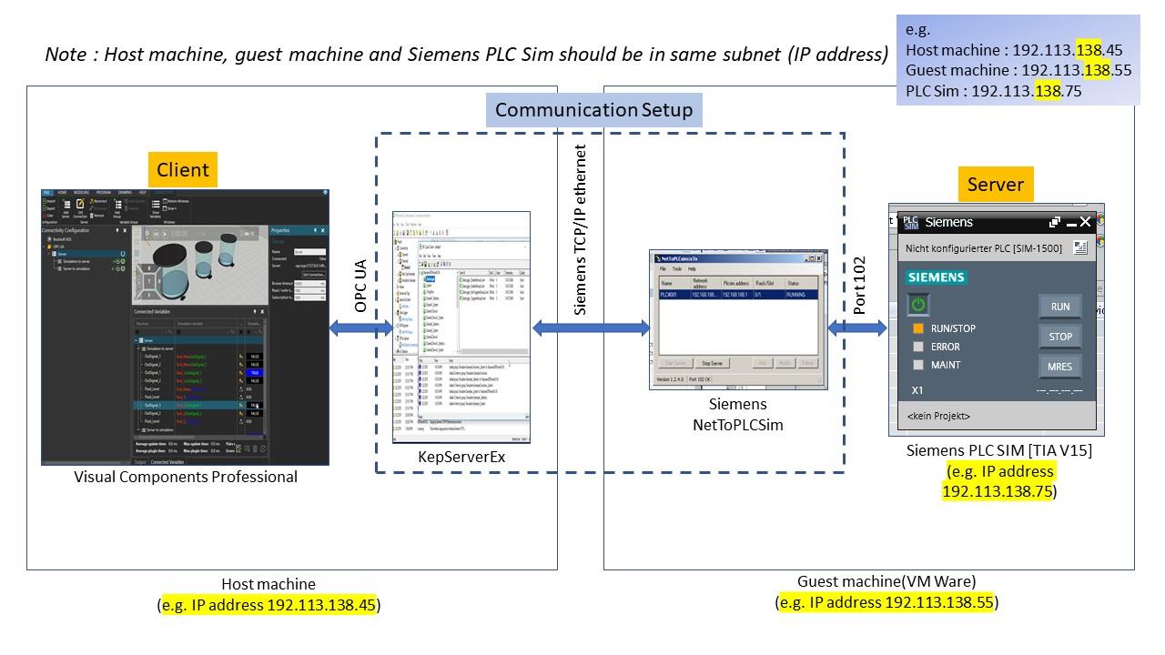
Check your IP address for PLCSim and the computer(where this is installed) have same 1st,2nd & 3rd octet but different 4th Octet, or simply to say in same subnet.
Ping from the other computer(where VC & Kepserver are installed) to the PLCSim of this computer.
Make sure you are properly connected to KepServer from VC via the OPC-UA interface. Check with the Quick Client of KepServer your connection is ok. Make sure your KepServer ir Running, your VC Simulation is running. Ping to this computer from the other computer.
The third point I am not really sure with the IPs.
My laptop has an IP address. Which IP address is getting the PLCSim in the PLC settings and which IP address is getting the NetToPLCSim server? Does PLCSim and/or NetToPLCSim needs to have the laptops IP address; or are those freely choosable as long as I am in the same address area of the 4th octet? (I am familiar with the IP address foundational knowledge )
The same question refers to VC and Kepserver the same
Does PLCSim and/or NetToPLCSim needs to have the laptops IP address?
ans:
*NetToPLCSim does not have any IP address, you can consider it as a tunnel which enables outside world to connect to “Siemens_PLCSim”
*Your laptop and Siemens_PLCSim must have seperate IP address but in same subnet e.g. 192.168.2.101 & 192.168.2.102
I am currently doing a very similar project and I found this post really helpful! Thank you for this detailed guide.
However, I have come across a problem that I hope you could help me out.
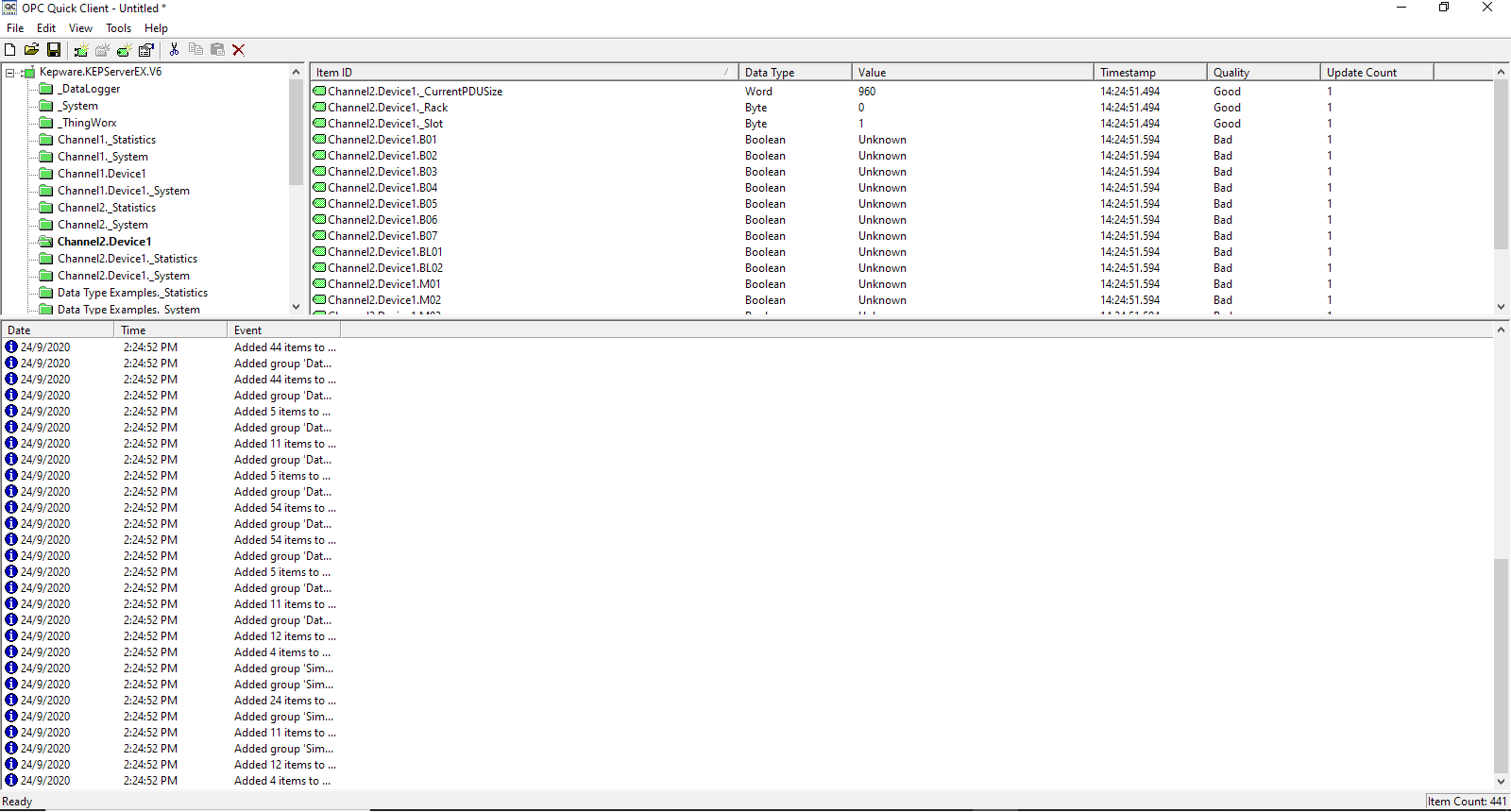
I am currently using KEPServerEX v6 and Visual Components 4.2.2. I followed your tutorial step-by-step and I noticed that the tags I created however has a quality status of “Bad” as reported in the OPC Quick Client utility supplied by Kepware.
This has also further included issues to the pairing of variables. As “Bad” quality tags cannot be written/read in Visual Components, as an error will be given during simulation.
I would like to ask for help on how to create “Good” quality tags in KEPServerEX v6? I have fitted a few pictures as reference to my current situation.
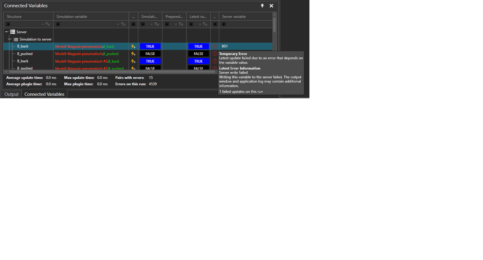
In the Temporary Error tab of Visual Components said that maybe the Output panel would explain the error a little, however nothing is shown in the output tab.
If there are anymore further information you require, do let me know.
I hope you could help me out on this.
In OPC UA terminology, the quality (status) of a variable is used to communicate whether the OPC UA server was able to read or write the value to / from the source.
So in this case the bad variables are configured somehow incorrectly and the KEPServerEX was unable to read or write them from the PLC. This could be due to wrong tag name, incorrect data type, the PLC refusing access etc. The driver documentation from Kepware may have for more useful info on how to troubleshoot the issue.
 with Visual Components Pro")
 with Visual Components Pro")

 )
)