Im using two positioners and 1 robot. Ive sent up the interfaces for both but it will only let me connect one positioner to the robot. Im looking to make them rotate separatly but only use the one robot between them both. Is that possible?
1 Like
Hi @TNR19,
Yes, you can connect multiple workpiece positioners. The interface in the robot must be “One To Many” and in the positioner “One To One”, please check that first.
You can check any robot and positioner in eCatalog for reference.
Ok, im having trouble connecting a Ferris wheel postioner that I’ve created the axis’s on. I pulled in a model and made the two table servos and main sweep servo rotate. I set them to one to one interface. I brought in a fanuc robot and changed it to one to many interfaces. Still for some reason it will not let me connect all three axis’s to that one robot.
To start, select your robot, and then open the Connect Interfaces command. Notice the robot has an interface for connecting workpiece positioners.
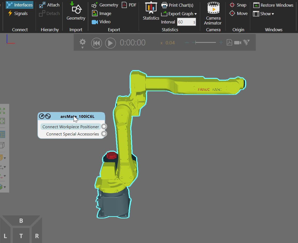
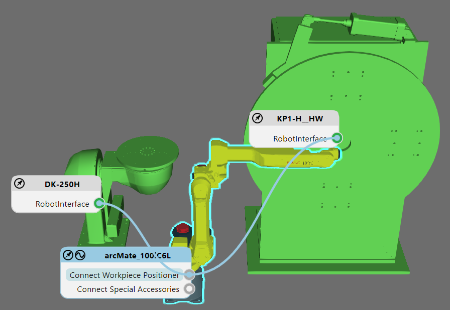
Now add the positioners you want to use and/or model them. If you open the Connect Interfaces command again, you should be able to connect them to robot based on the selected interface. Notice in the image I have the workpiece positioner interface of the robot selected.
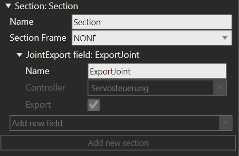
If you are unable to do that then I would suspect the Interface > JointExport field has configuration issue. The interface on your workpiece positioner should look something like this. (JointExport field, controller of the axis is defined, and the Export field is turned on)
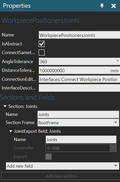
Why does that matter? The interface on the robot for connecting to workpiece positioners is expecting that since it also has a JointExport field, the controller of the robot is defined, and the Export field is turned off)
In a nutshell, the interface on a workpiece positioner should be One to One. The interface on the robot for connecting to workpiece positioners should be One to Many if you took Fanuc robot from the eCat. You should not have had to change the interfaces.
If you don’t want to share your layout here, contact support. They can probably quickly resolve this for you.
Thank you! My issue was I had three robots and i was wanting the three axis postioner connected to just one robot. I deleted the extra two robots out and it finally gave me the option to connect all three axis to one robot. I connect them to the one robot and then added the other two robots back in afterwards and it worked. I don"t know what that’s what it took but it seemed to work,
That sounds like a bug. What Fanuc robot were you using?
I was using the ARC Mate 120iC/10L
Tested with the robot. No bug. What might have happened is the interface in the positioners already had connection, e.g. to the other two robots. So deleting them removed the connection and freed up the interface in each positioner for one-to-one connection.
More than likely you are probably right. I am new to the software and with the help of some power point slides I am trying to kind of teach myself.
if it helps, i can suggest a learning pathway of academy lessons and help topics. Just need to know if you need to do any modeling, programming of robot, connectivity, or focus more on layout configuration. what you experience in your original post is common since one-to-one and one-to-many interface connections could have better user experience than just coloring a component grey, yellow or green.
That would be awesome! Would love some more information on connectivity.
Learning Path for Connectivity
This path is meant for users that have Visual Components Professional or Premium. If you take this path it is assumed you are interested in validating PLC programs, connecting external systems, controlling robot with PLC, and making digital twins. Generally, this involves layout configuration, some component modeling, and connection and mapping of signals/variables with other systems albeit scripts or Connectivity features.
Hope it helps, and happy learning. And if you need another resource, consider this blog.
https://blog-gallopautomation.com/connect-visual-components-sw-to-siemens-s7-1200-plc-via-kepserver/
Basics of Simulation
Overview of basic functionality, e.g. 1 hour demo
http://academy.visualcomponents.com/lessons/basics-of-simulation/
Connect Interfaces
Just double check you have the gist of connecting external axes to robot and special accessories
http://academy.visualcomponents.com/lessons/connect-interfaces/
Make a Simple Conveyor PLC Ready
Import CAD file and use signals to turn on/off behaviors like paths
https://academy.visualcomponents.com/lessons/make-a-simple-conveyor-plc-ready/
Model a Workpiece Positioner
Import CAD file and use a Wizard to add needed behaviors
http://academy.visualcomponents.com/lessons/model-a-workpiece-positioner/
Machine Tending using Feeler Machines
Basic layout configuration
http://academy.visualcomponents.com/lessons/machine-tending-using-feeler-machines/
Machine Tending using Different Libraries
Basic layout configuration with other libraries, but please consider this option since you should try to use process modeling going forward since Works library is now considered old library, whereas process modeling is new way to define processes.
http://academy.visualcomponents.com/lessons/machine-tending-using-different-libraries/
Model a Raycast Sensor
Doing tutorials on other sensors might also help. Note that having many raycast sensors in simulation can affect performance
http://academy.visualcomponents.com/lessons/model-a-raycast-sensor/
Import and Combine Different CAD Files
Just a review of cases in which you need to import geometry and structure it in models.
http://academy.visualcomponents.com/lessons/import-and-combine-different-cad-files/
Control Servos
A bit outdated but the basics are there. Note that there is a way to name a joint and signal to work together. For example, a link with a joint named DoorJoint, and a Boolean signal behavior named DoorSignal to track when the DoorJoint is at max value or min value.
Component States
Basic workflow for adding states to a component. For connectivity, you often need to do some modeling in a component, so good to be aware of some things.
http://academy.visualcomponents.com/lessons/component-states/
Component Script
Brief introduction to using Python Script behaviors in a component, which allow you to create custom behavior.
http://academy.visualcomponents.com/lessons/component-scripting/
Event Handlers and Conditions and Signals
Outdated. Please check Help file for better explanation of triggerCondition() and condition() in which condtion() is evaluated immediately and then with each subsequent trigger, whereas triggerCondition() waits until first trigger to evaluate the condition.
http://academy.visualcomponents.com/lessons/event-handlers/
http://academy.visualcomponents.com/lessons/conditions-and-signals/
Joints and Degrees of Freedom
If you need to control robots with PLC, good to have a basic understanding of DOF objects in Visual Components 4.x.
http://academy.visualcomponents.com/lessons/joints-and-degrees-of-freedom/
Physics
You might need to know basics of using physics in simulation, e.g. for material flow use cases.
http://academy.visualcomponents.com/lessons/physics-entities-and-colliders/
http://academy.visualcomponents.com/lessons/model-a-physics-feeder/
http://academy.visualcomponents.com/lessons/model-a-physics-conveyor/
Connectivity
The lessons are mainly about the features and how to enable them. The mapping, establishing connection and monitoring are more or less the same.
https://academy.visualcomponents.com/category/lessons/connectivity/
The OPC UA server tutorial can be considered basic introduction.
https://academy.visualcomponents.com/lessons/connect-a-remote-opc-ua-server/
Webinars
There is no webinar on connectivity as far as I know, but here is a link to them. Perhaps the Component modeling webinar would be of interest or the Python API one.
https://academy.visualcomponents.com/webinars/
Older tutorials
Here are really old tutorials made in previous product versions. The UI and workflows are different, but if you have a basic understanding of connectivity in VC 4.x then you can make sense of them. Note that the modeling standard and naming conventions in those components may differ than the ones used today.
LearningPath.zip (17.7 MB)
1 Like
Thank you! I will begin to go through it when i have extra time to do so.
Hello,
Is it possible to use this kind of connection in OLP?
Thanks in advance!