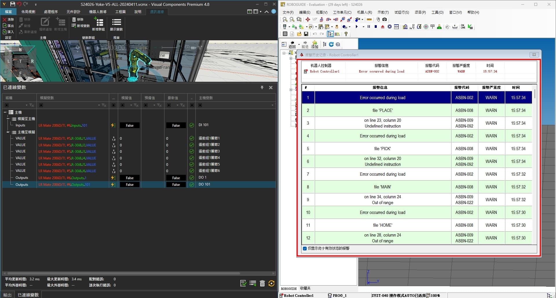
I’m encountering some issues while attempting to synchronize Visual Components (VC) with Roboguide, and I’m hoping to find a solution here. I’ve successfully established a connection between VC and Roboguide, and I’ve verified that all joints and signal connections are set up correctly. Additionally, I’ve used the VC plug-in “Program Post Processor” to convert the arm’s positions into .LS files. However, when I attempt to import these programs into Roboguide, I encounter errors. In fact, any program containing positions cannot be imported smoothly.
I’d like to ask for your advice on how to resolve this issue. I suspect there may be some steps or settings that I haven’t correctly executed or configured. Could anyone provide me with some suggestions on where to start checking to solve this problem?
Check the ReadMe of the PostProcessor add-on. It has some information about different brands. Many times with Fanuc problem is unsupported tool or base frame in motion statement. ReadMe states which ones should be supported.
Assuming you’re using the same Post Processor I am, it will produce a .LS file for each robot program you have in VC, and a SETFRAMES.LS file. The SETFRAMES.LS file must be run first, to set all the UTOOL and UFRAME values.
However, I’ve noticed that VC tends to like using very high numbers for UTOOL and UFRAME, higher than the default size of the arrays in Fanuc controllers. So I often have to do a Cold Start on my Fanuc and increase the size of the UTOOL/UFRAME arrays before I can run SETFRAMES.
I’ve also run into some issues with the way the Post Processor formats Config values, at least for 4-axis robots. So far, every Point value I export needs to be hand-edited to fix the Config values:
VC "default version:
P[1]{
    GP1:
         UF : 25, UT : 1,              CONFIG : 'N U T',
         X =     0.00  mm,     Y =   395.30  mm,     Z =  1298.28  mm,
         W =   180.00 deg,     P =     0.00 deg,     R =   180.00 deg
Fixed version:
P[1]{
   GP1:
	UF : 25, UT : 1,		CONFIG : 'U T, 0, 0',
	X =     0.000  mm,	Y =   395.300  mm,	Z =   543.700  mm,
	W =   180.000 deg,	P =     0.000 deg,	R =   180.000 deg
I hope this email finds you well. I wanted to extend my heartfelt gratitude for taking the time to respond to my post on the Visual Components forum regarding the challenges I’ve encountered with the post-processing of my .LS files. Your insights were incredibly helpful, and I truly appreciate your willingness to share your expertise.
After reviewing your suggestions, I’m eager to delve deeper into the process of modifying my .LS files effectively. Specifically, I would greatly appreciate any guidance or tips you might have on correctly adjusting the .LS files or identifying and rectifying errors within the program.
Based on your previous response, it seems there are nuances in handling UTOOL and UFRAME values, as well as Config values for 4-axis robots, that I need to better understand. Would you be able to provide further clarification on how to navigate these aspects effectively?
Additionally, if there are any resources or best practices you recommend for post-processing in Visual Components and synchronizing with Roboguide, I would be eager to explore them further.
Once again, thank you immensely for your assistance and expertise. Your support is invaluable to me as I strive to improve my skills in this field.
I’m afraid I’m hardly an expert in this area. The good thing about .LS files is that they can be edited in any ASCII text editor, so doing a mass search&replace of certain patterns isn’t hard. I usually just open all the .LS files in NotePad++, build my search term, and use the “replace in all open files” option. Depending on the complexity of the S&R, you may want to look into the use of regular expressions.
If running SETFRAME throws errors on the robot, then you need to perform a Cold Start, then change the system variables $SCR.MAXNUMFRAM and $SCR.MAXNUMUTOOL to something equal to, or higher than, the highest UT and UF values used in the LS outputs, then reboot. However, on some older robots making these values too large may cause issues, so the alternative would be to do a search&replace of all the UT and UF values to something that fits into the robot’s existing array length.