Hello,
as you can see in the title, I’d like to understand how to make program/cell “the right way” in VC. Our cell looks something like:
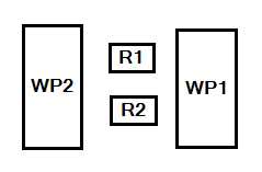
On the real cell, the way we do it is:
- 1st case:
- We use R1+S1 and R2. R1 is master of S1 and external axis orientation is constant while welding(We also swap R1 and R2).
- 2nd case:
- We only use R1 + S1(Synchro).
- 3rd case:
- We only use R2 + S1(Synchro).
- 4th case:
- We rotate S1 to position, then use R1 and R2 separately.
- I know we can do this with “multirobot controller”, but then we’re unable to use first 3 cases.
At the end we can either have program with only R1/R2 data and S1 data separately or R1/R2 and S1 data together. That’s a very common way of programming, as far as I know or have seen, but me and my colleagues just can’t find a simple solution for how to do it. We’ve been playing back and forth with connecting and disconnecting interfaces and exporting/importing (or cloning) programs, trying to somehow trick the VC.
When we add a second workpiece positioner, everything becomes a mess. I tried to use the “one to many” interface, but all of this feels so complicated and there’s no proper manual on how to set it up. There are so many advanced options you can set, but a simple toggle to use external axes when the robot and workpiece positioner are connected isn’t one of them. Or at least, if we have to use external axes while programming, we could export(or maybe download) the job without them.