hi~
I got to know about physics cable, watching video.
However, I do not know how to layout and use this cable.
I would like information about this cable.
(The program I am using is Professional 4.1.)
hi~
I got to know about physics cable, watching video.
However, I do not know how to layout and use this cable.
I would like information about this cable.
(The program I am using is Professional 4.1.)
It is recommended that a physics cable be its own component, so create a new component and add a physics cable behavior to it, and then save the component.
From there, add more pins as needed to make the cable stable and bendable at certain points in its length. That is, create a new node for every additional pin needed. How? Use the two pin nodes as a reference and follow the naming convention, e.g. Pin_3. Those two pin nodes are added automatically for you when you add the Physics Cable behavior. Each pin requires a physics entity behavior and needs to have the right name.
Refer to the Behaviors Reference and Tasks > Physics sections of help as needed about the properties. You can also refer to the Nvidia Physx link provided in the Help as well as the Unity reference guide since both software use Physx. How the properties are implemented may differ, for example different default values.
However, customizing the cable is the hardest part and requires testing on your own. First, move the first and last pins of the cable to the needed anchor points. That is, go to Modeling tab, and with a pin node selected, use the Move tool to drag the pin to the desired location. Next, set its Anchor property. You could also try using the Attach command to set that property. But note that attaching won’t move the pin! After the anchor points are set for the beginning and last pins of the cable, run the simulation and see how the cable moves in its default state when affected by gravity. I believe the end points hang and swing by default, but I don’t remember. Anyway, the cable has properties for defining how the end points should move, e.g. swing like a drawbridge, fixed like a connected/coupled joint, or have some movement like a tensioned chain side rail of a bridge.
Reset the simualtion as needed to return to the initial state of the cable. From there, adjust the stiffness of the cable itself and run the simulation and move the robot through a simple program to see how the cable moves. If you see some bubbling or breaks in the cable, it is either too stiff or not long enough. Note that a cable consists of capsules, small oval shaped geometry generated along the length of the cable. If the Length property of the cable is zero, the length is automatically calculated based on the end points, etc of the cable. In some cases, you can try giving a fixed length. But to avoid breaks, consider testing the tension and velo/pos iteration properties to get the needed result.
It is a challenge, my friend, so for cables consider using geometry instead of the physics cable for robot dress packages. For example, use one of the KUKA robots in the eCat as a template for creating your own cable from geometry.
Hello all,
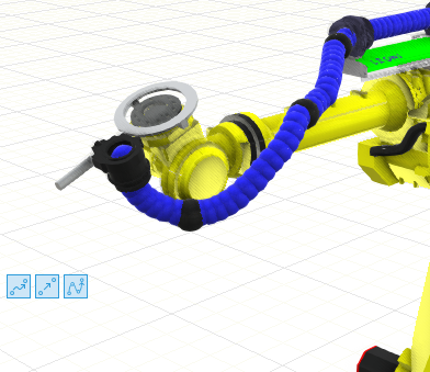
I have the following problem: I inserted a cable for the simulation and the cable goes through the robot arm during the simulation.
is it possible to adjust it so that the cable behaves like a full body? So you don’t want it to stretch through the robot arm? (see picture)

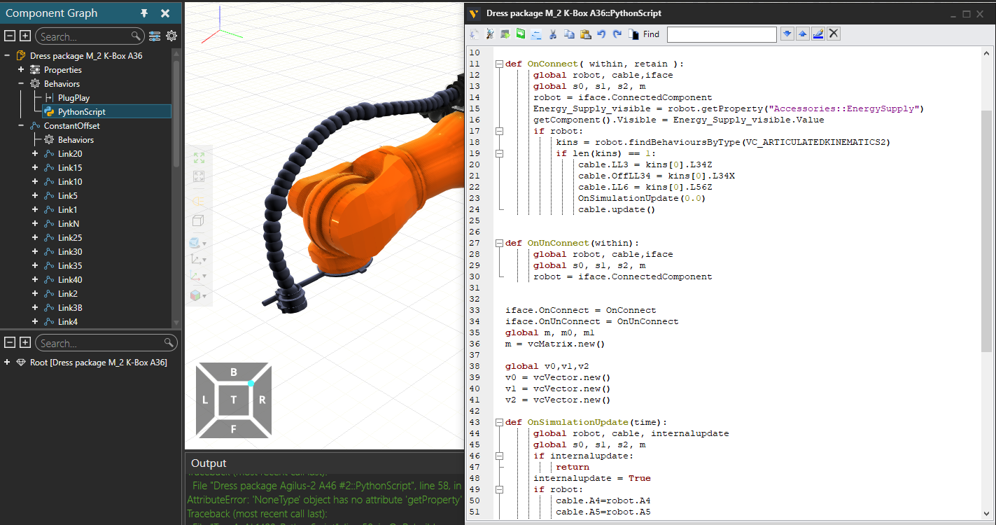
Hey @WilliamSmith I am trying to accomplish what you mentioned on your post about impolementing the dress out component used in the Kuka robots in other robots.
however I am fairly new to Visual Components and could use a point in the right direction.
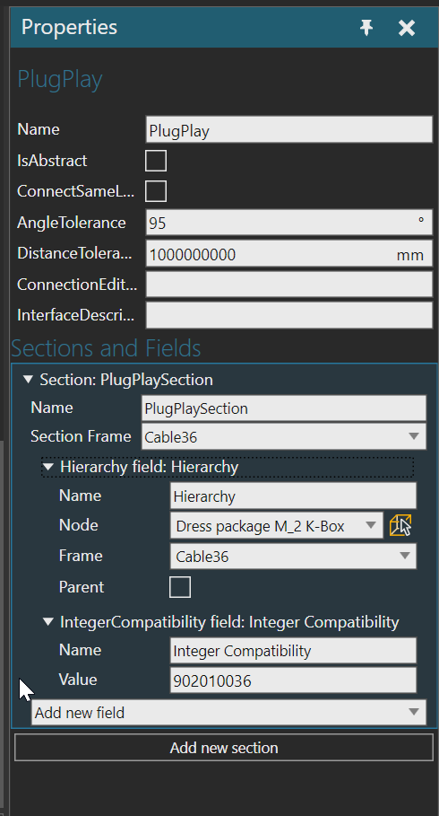
I see on this component here we have a plugPlay behaviour I tried to disconnect it from the Kuka robot
with the PnP tool which worked.
I then created a frame with the same name on my fanuc robot with the same name as the one used in the KUKA robot “Cable36”
I then tried to connect it to the fanuc robot and it looked like it wanted to try to connect for a second but then it never did.
I am trying to figure this out but any help is appreciated i know you guys are pretty busy but would really appreciate any input even small nudge in the right direction.
for example do i have to do changes to the python script?
do i have to add behaviours or properties to the robot?
any help is appreciated
thank you
I don’t know what KUKA robot you are using, and dress packages in general are not searchable in eCat. The dress package you are using most likely has PnP interface with Integer field. Generally, an Integer field is used for compatibility issues and to filter what can and cannot be connected to one another. For example, dress package for a KUKA robot probably cannot be plug and played to Fanuc robot unless there is another curve ball thrown by 2020!
In your dress package, remove the Integer field and/or add interface to your robot for connecting the package with the needed fields and values. With any connection, ensure the fields are in same order as well.
Other than that, physics cables are still not widely used for eCat components, so most dress packages still use a combination of transformations, expressions and sphere primitives.
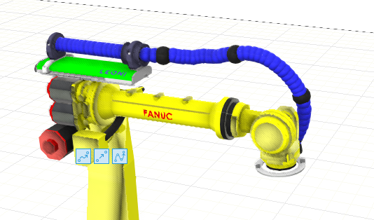
@WilliamSmith I got it working!! just wanted to show you and say a huge thanks for the help
you are the man!
thank you for replying to an already old thread. as you can see I have it working with my fanuc robot now. is not perfect the movement is a little bit weird at times as you might see it probably has to do with the formulas they used in each joint. but I’m ok with it as I get better at Visual components I hope to be able to improve it.
Good to hear. Yes, the movements will be a bit weird, specifically around joint turns/limits. Someone from support can probably help you improve the movement/give some best practices for modeling the cable since folks in support also update the eCat.
Can you provide relevant tutorials?
@CarlosPlazas could you share how you were able to get the simulation to work?
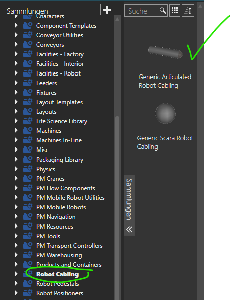
@jmoney , As a note, there is a new component “Generic Articulated Robot Cabling” in eCat 4.9
Hi WilliamSmith,
you said “add more pins as needed to make the cable stable and bendable at certain points in its length. “
Could you tell me how to add pins to a cable in Visual Components?