
Hello,
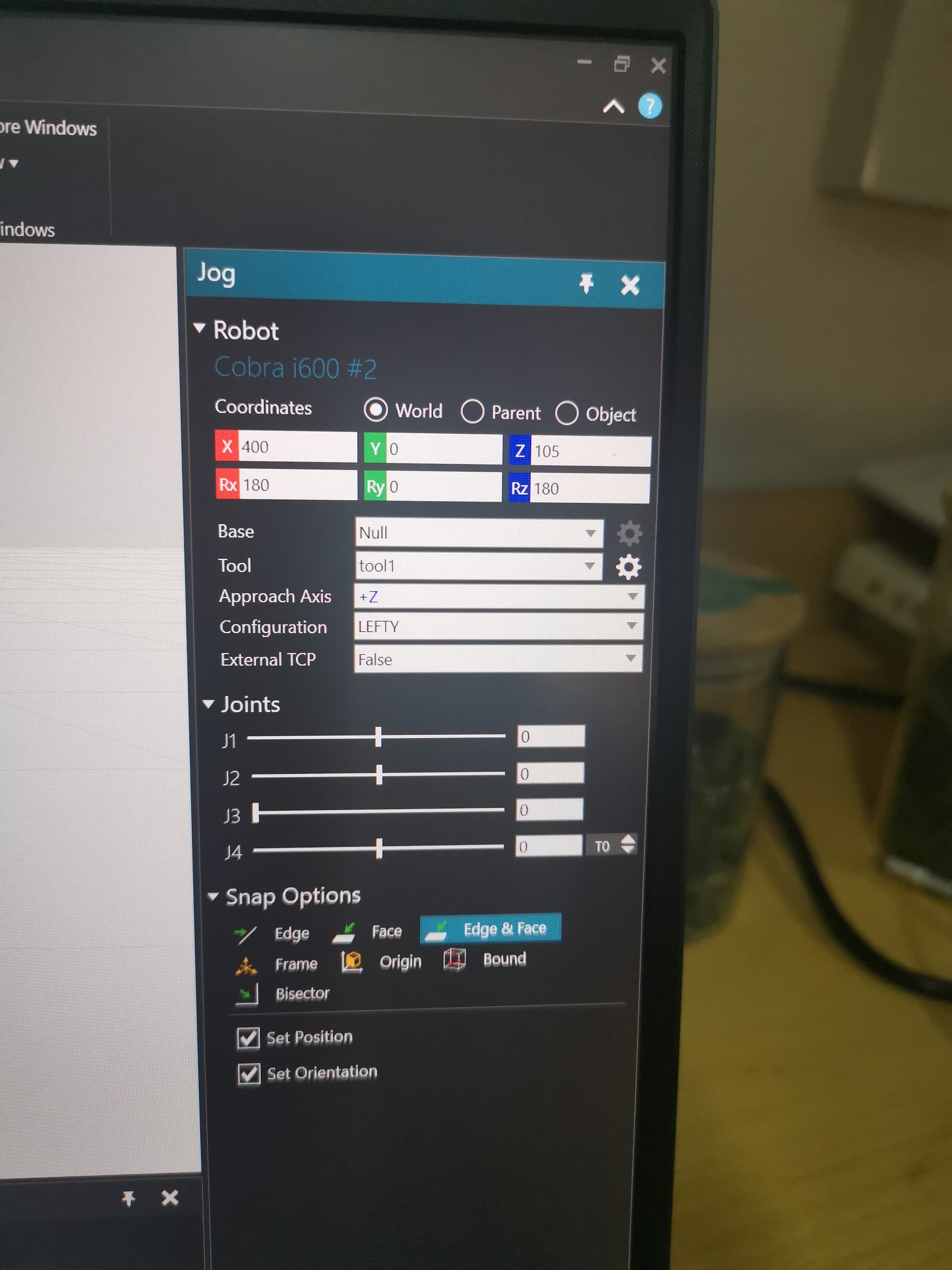
Hard to tell with pictures alone, but I can replicate this problem by first moving the tool1 frame to somewhere else. Figure 1 shows this.
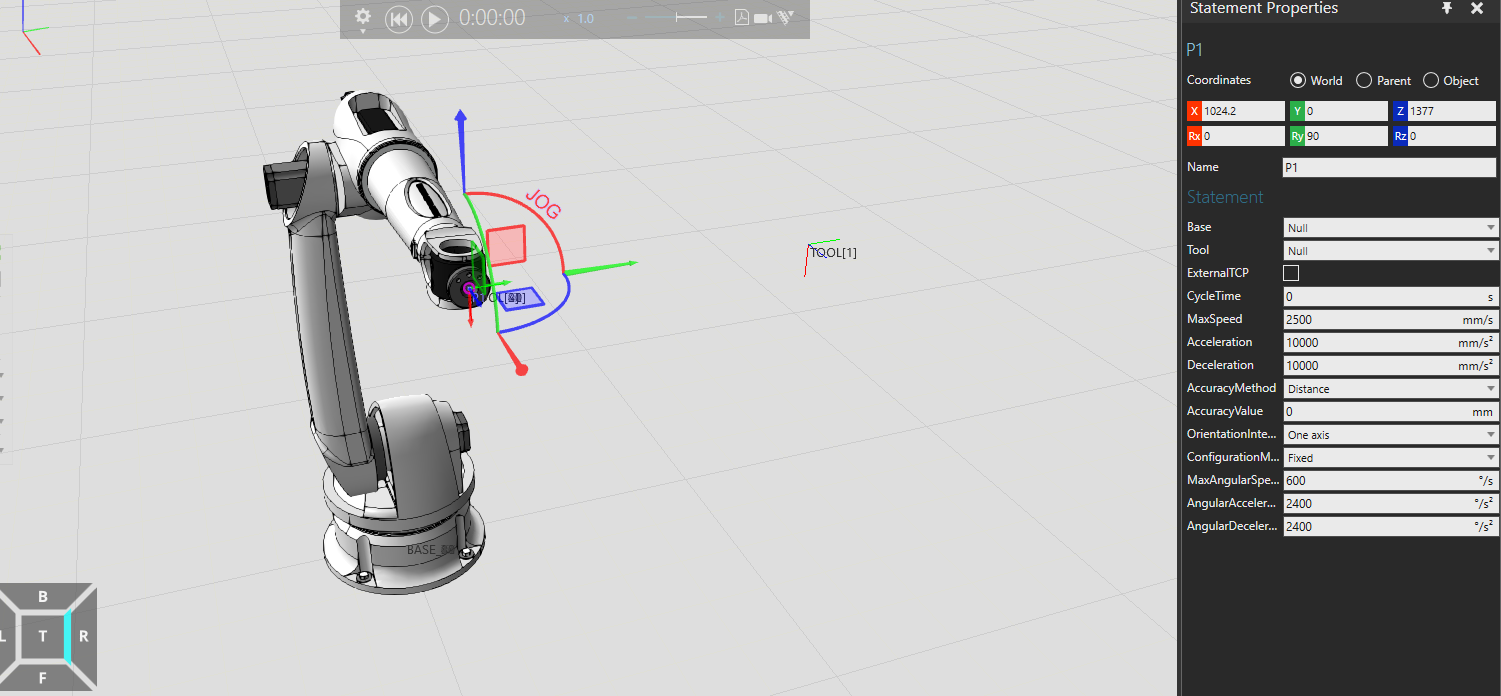
Figure 1
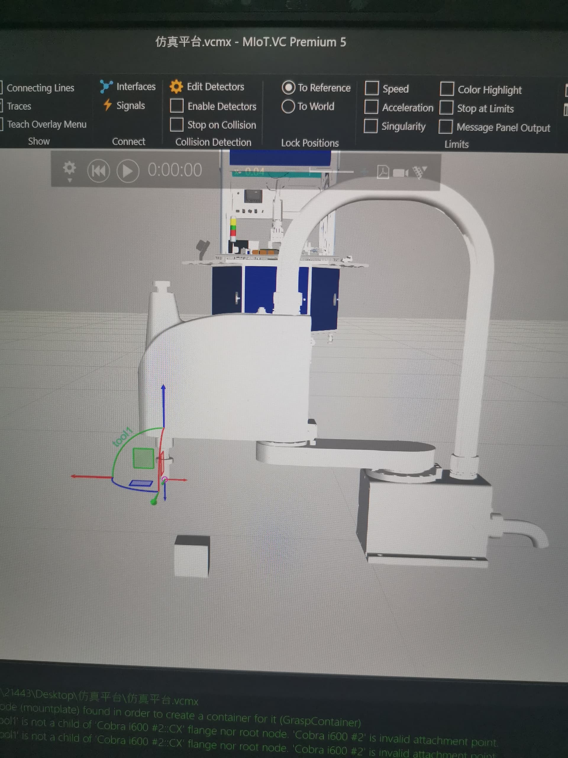
After this I can change from null to tool 1 and I get the same problem seen in figure 2.
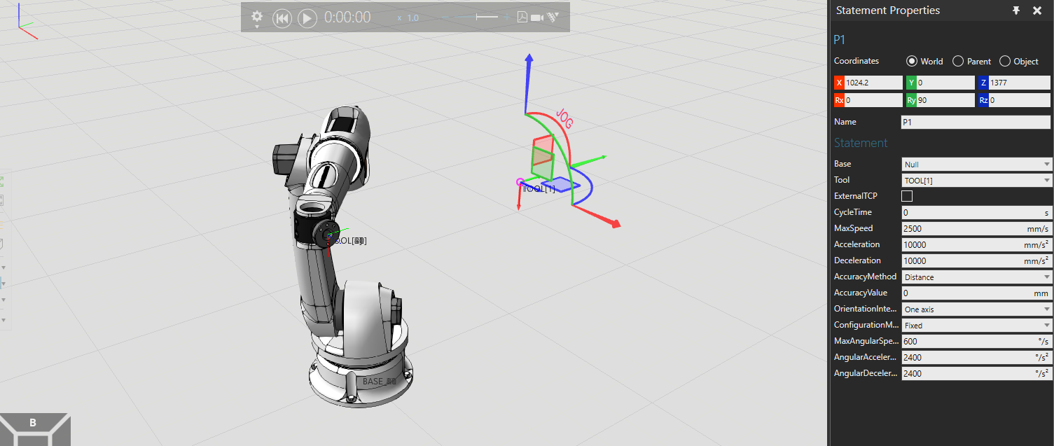
Figure 2
so,bro,how to solve or avoid this problem?It bothered me for days and prevented me from working on the next step.thank you.
Hey,
I just moved the tool frame at the correct position (VC pro or prem needed). You could also send your .vcmx if possible and I can probably solve it, no promises though!
bR
Lefa
data simu.vcmx (9.8 MB)
thank you.
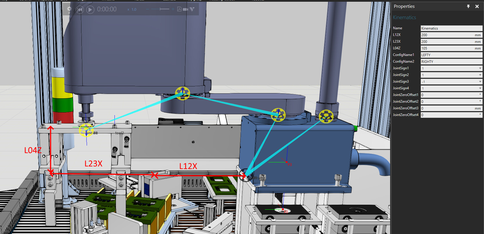
Robot is not modeled correctly. It uses inbuilt scara kinematics solver but the node structure doesn’t respect the same link offsets. In the following picture you see the link offsets that the kinematics expects (L12X, L23X, L04Z) but the node structure is done differently. As a result you see the TCP jog handle at the location where kinematics solver calculates it and it’s out of sync with the actual link scructure.
If I were you I would start modeling again based on some functional eCat scara. Don’t touch tempalte robots link offsets but only modify the lengths on the kinematics. Change your robot CAD origin so that 1st joint rotates around origin Z axis and you don’t need to offset it’s pivot point.
Here’s a quick video showing how to get started with modeling a new scara. I have the CAD and first I modify its origin at the center of J1. Note that while using move-tool and dragging object along some axis I press and hold CTRL key to get a reference from some geometry, in this case at the center of a joint or at the bottom plate. After setting the origin I replace CAD on some template robot and then I only modify kinematics lengths and not the link offsets. This way kinematics stays in sync with the node structure. Only if you change joint sign on the kinematics should you modify the link as well and change the joint axis there also. And of course the follower joints like the cable need to be solved manually by setting out the link origin and figuring out the math expressions for the joint.
-k
1 Like
Thank you, your answer solved a lot of my problems, it means that the shape of the nodes should be the same, only the size is different.thank you
hey,brother.I want to make a pusher to push the block, the block below pushes out and the block above falls down.now,I donot know how to do next work.I looked for a lot of sites, including YouTube, it’s too hard for me, if you can teach me or give me a video site, I’d really appreciate it