I am currently facing an issue while doing Gripper Modeling. After importing my CAD file into the software, when I try to select the links or joints that should move, the program does not recognize them as a single link, but instead treats them as separate parts.
Because of this, I am not sure how to set up or organize the model structure so that the software recognizes these parts as one link.
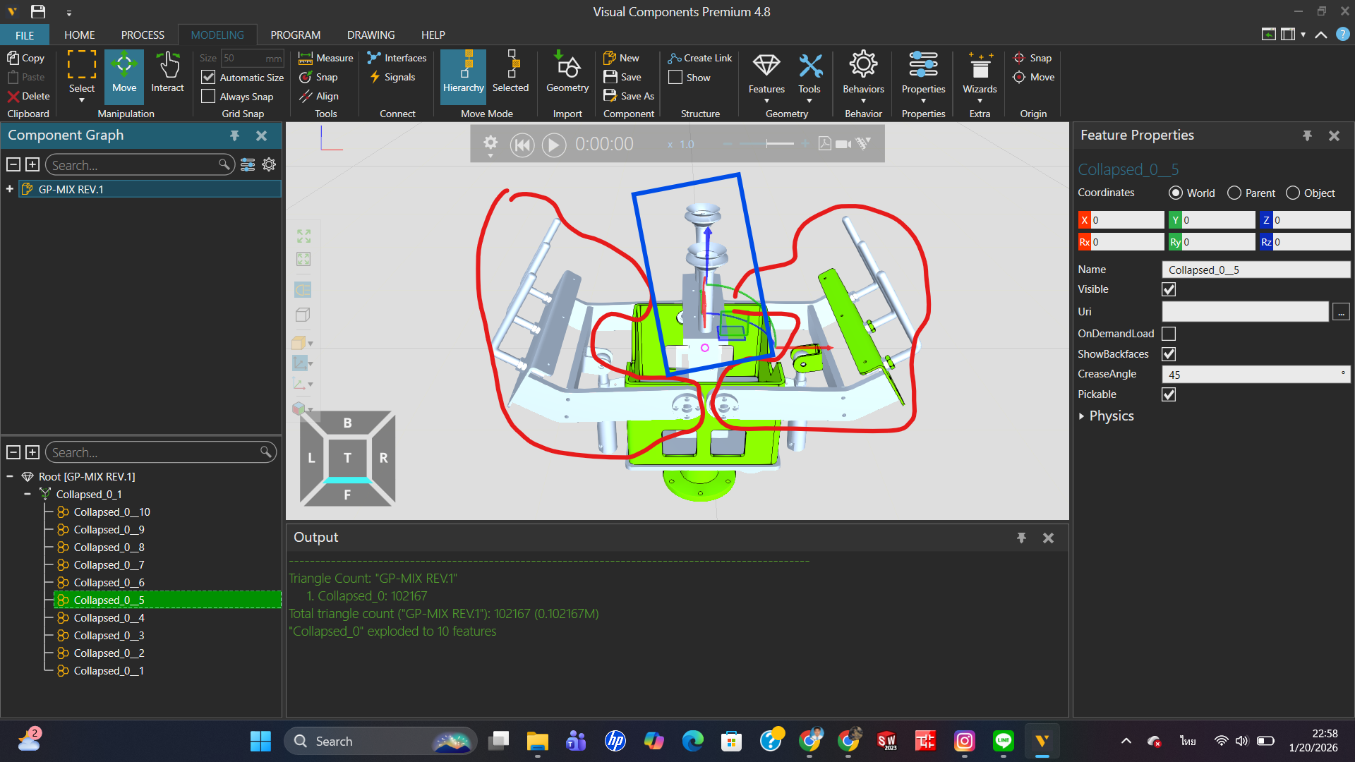
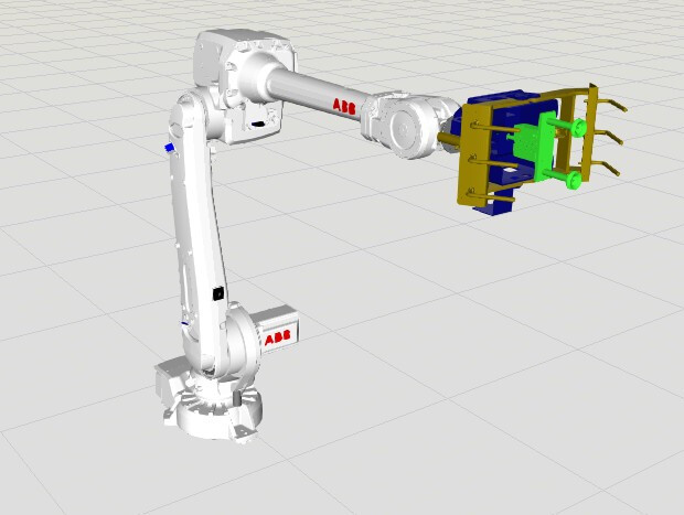
When the grippers close (the two red-circled points), the center part (the blue-circled point) moves upward. When the grippers open (the two red-circled points), the center part (the blue-circled point) extends downward.
I would like to kindly ask all experts who read this topic for your advice and guidance. Thank you very much.
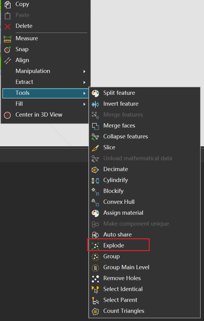
I didn’t quite understand what your main question was, so let’s go through them one by one. Because VC is different from other CAD modeling software, it’s more oriented towards software similar to visual effects (in terms of operational principles). So, general models that enter VC need to undergo CAD conversion. Any dependencies or issues that arise during modeling or conversion can be attributed to being outside the model. At this point, you can try the Explode option from the right-click menu, and the program will attempt to break the model down into more features. Of course, this method doesn’t always work, so it’s still important to pay attention to modeling habits.
Good answer @BAD. Also the Split tool is handy for separating a few specific geometries from a larger geometry feature: select Split and click on objects from the 3D world that you would like as a separate geometry feature.
If there’s only a few objects I need to extract into a different geometry feature, I prefer Split tool, as exploding a large geometry feature takes time (and increases component file size unless the geometry feature is collapsed again afterwards).
@bobby_RMUTTO67, you might have seen this tutorial already, but this one guides through modeling a robot gripper: Model a Robot Gripper – Part I | Visual Components Academy
Only difference is that now the gripper’s moving links should have joint type Rotational instead of Translational, and the links’ position must be where the rotational axes are, so that the links rotate around the correct axis.
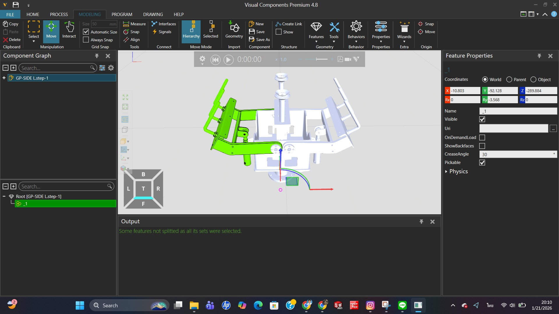
Hello, @BAD I have already tried using the Explode function, but the software still does not recognize the parts as a single link. I would like the program to treat them as one link,The desired result is shown in the image. Thank you for your answer. I would appreciate your further help. Thank you.
Hello @KustiH I have already watched this tutorial video, but when I tried to follow it, my result was not the same as in the video. I have never used the Split command before, but I will try using it.
Thank you for your answer. I would appreciate your help. Thank you very much.
I’m writing this message in bed because I’m ready to turn in for the night. If this doesn’t fully resolve your issue, you might need to explore solutions on your own or wait for replies from others.
First, let me add a supplement to my previous response. That method is a separation technique used when a component that shouldn’t be treated as a feature is incorrectly identified as one. I noticed you mentioned wanting to treat multiple elements as a single entity—to merge multiple features that weren’t originally a unified feature, you can use the Merge Features function, which is also located in the right-click menu I showed you earlier. Additionally, you can use Collapse on a moved feature to consolidate it into a single feature. Note that geometric element features and adjustable parametric features (such as squares, circles, etc.) cannot be merged directly using Merge Features. You need to first convert parametric features into geometric element features via Collapse before proceeding with the merge.
This is my response to your question about “treating elements as a single entity.” I’m not sure if it fully addresses your needs, but I can confirm that this method is effective.
As a side note, to generate a link, you also use the right-click menu—but it’s not under the Tool submenu; instead, it’s found in the Extract option as Extract as Link.
If I’m interpreting your question correctly, you don’t need to merge the moving parts into one geometry feature. The geometry can stay in multiple pieces, what matters is that everything meant to move together is placed under the same joint.
Use Explode or Slice to break the CAD into the pieces you need. Then select the parts that should move together and Extract as Link. Anything under that link will move as one.
From your image, you’ll likely want the left and right gripper sections as two separate links. Then apply a Rotational Follower to one link so both sides stay synchronized.
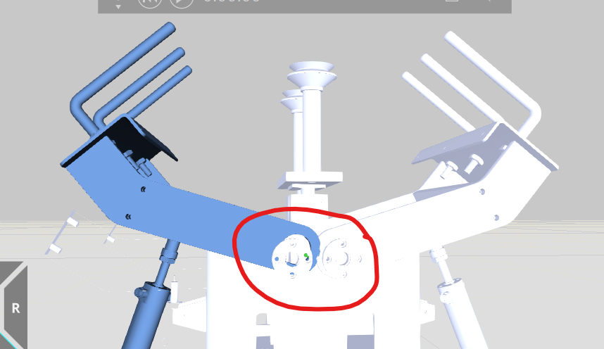
็้้Hello @mkittell Thank you for the explanation. I would like the pivot point to stay within this bearing and not move out of it. What should I do next?
In the robot properties, find Action and set the port you use to 100. Generally speaking, the first several points (1 to 60 or 1 to 88?) of robots in the library are default settings. You can check this part, of course, these are all in Academy. You can refer to this link (though it’s quite old):