Hello,
I have two similar questions and need your help.
Arrays a large number of “frames” in a component. My idea is: first create a “Frame”, then determine its specific coordinate position, Finally, the X, Y, and Z arrays are executed;
Offset a “Frame” in the component. Whenever the signal is triggered, the “Frame” is shifted by a certain distance.
I suspect there are much better ways to achieve your end goal than actually defining all the positions as frame features. For example, in robot programs you can move the coordinate base, or you can use a transform feature to define frame feature’s position using a matrix expression you can manipulate through component properties. With scripting you can also just calculate any position matrix and use those directly for most things without needing frame features.
You would need to generate and update array of frames using a script because the linear clone feature doesn’t seem work for frame features.
Moving the frame features would be quite slow since you need to run component rebuild every time. An efficient way to move them all would be to make one or more joints in the component and move that.
Realize the function of passively detecting the presence or absence of each material level
Passive detection: Manually specify the material level in the attribute and return information about whether the material level has material or no material.
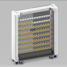
In the picture, the electrode material rack has a total of 112 material levels. At present, a coordinate frame, a Boolean signal, and a ray sensor are added to each material level to implement the function of passively detecting whether there is material or not in each material level.Because I don’t want the scanning frequency of the ray sensors to be less than 0.1 seconds, these ray sensors take up a lot of running memory in the background scanning, resulting in the problem of running simulation slow.
I tried the following methods to solve the problem:
use a ray sensor plus 112 coordinate boxes (the default coordinate box has been defined on each material level), and bind the corresponding material level coordinate box of the ray sensor through the specified material level, so that the ray sensor can detect at different material levels, This is why I asked how to implement the array of coordinate boxes, but I have tested this method and the results are not ideal, Even if the material level I specified is material, it also feeds back information that is not material, The feedback is correct only when I specify this bit for the second time (after the first designation, the coordinate box is stuck in the current position before the simulation is run without a reset), This may be because the ray sensor updates the bound coordinate box slowly. I try to add a delay under the update ray sensor coordinate box statement that defines the function to wait for the ray sensor update to complete before outputting the test results, But adding a delay to the function has no effect. No matter how long I add the delay, it always outputs the result immediately.
Use a ray sensor and a coordinate box, and offset the coordinate box to the specified material level, so that the ray sensor can detect at different material levels, 2) This is why I asked how to achieve the offset of the coordinate box, but the result is the same as test 1).
Use a ray sensor to add a coordinate box, but instead of shifting the coordinate box to the specified bit, add the coordinate box to a new joint, By offsetting the joint to the specified material level and indirectly offsetting the coordinate frame to achieve the detection of the ray sensor at different material levels to verify the “TSy” method, the result is still the same as test 1).
It would be much more efficient to have a “component container” behaviour in your material rack and have some other logic place and remove the material components there when the components are physically moved in and out. For example the robot grasp and release actions can do that.
With the component container you can then have a Python script in your material rack subscribe to the vcContainer OnTransition event and in that event handler use the component position to calculate which slot the component was added to or removed from. Once you know the slot you can e.g. trigger a corresponding signal behaviour.
If you really need to have this be “passive”, then having separate volume sensors for each slot should still work with decent performance if you set them up correctly. I suspect that generally the performance issue you are facing is coming from repeated world updates or component rebuilds.
Assign same SampleTime to all of them and “UpdateScene” Enabled only on the first one to avoid unnecessary world updates
If a volume sensor is used, two frames are required for one sensor. Since a frame cannot be created in an array, defining a frame will be a considerable workload.
But your last suggestion reminded me that I hadn’t noticed this before. I cancelled UpdateScene, TestParent, and ShowRay of the ray sensor and it solved my problem well.