I’m currently working in Visual Components Premium OLP 4.10 and trying to model a conveyor based on an imported CAD file (geometry only, no behaviors).
Don’t have a solution, but I tried this myself and attaching components is inconsistent even if you take the conveyor piece from the Academy tutorial. I’m not sure what logic it uses to decide which ports to connect, if there are multiple.
@hanslow not sure if you already resolved this question. Meanwhile I was discussing this with VC support and was able to get some useful information on the topic. They also mentioned the academy lesson might need an update, since it’s several VC versions old at this point.
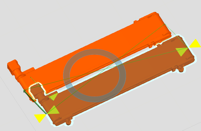
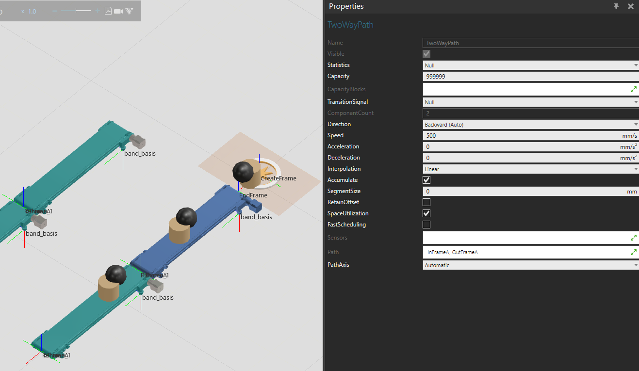
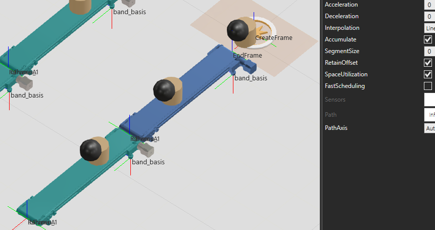
Have a look at the attached example (orange piece is your original, blue is changed) band_bidirektional (1).vcmx (990.5 KB)
Changes done:
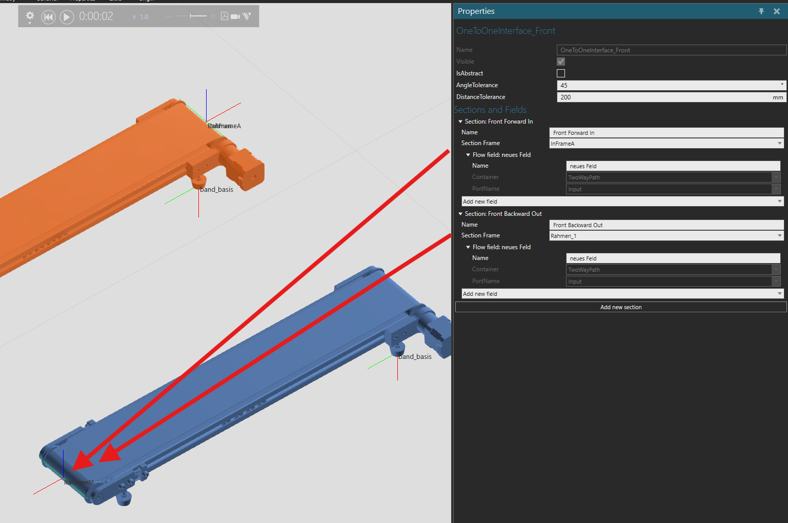
Change both interface AngleTolerance → 45 and DistanceTolerance → 200. This makes the PnP connection much more consistent with the ports you want to connect.
Changed connected frames, changed interface naming slightly for clarity. Consider that one interface is always at a certain point on the component. Both frames (in frame one way, out frame other way) should connect to the same port of the interface.
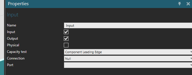
In this case the “front” interface has both frames connected to the input port of the path (and under the path port properties the port is set to act as both input and output).
The frames acting as the section frames do not need to be in the path itself. (as you can see path is defined by 2 frames, but in the interfaces, there’s a total of 4). During the transition the product teleports from the port to the start of the path.
By default, products entering from the other direction flip 180° as they get moved from the port to the start of the path. To keep their orientation (both xyz and rotations), set RetainOffset → True in the path properties.